Another thought raised during the meeting was the extension of the project hypotheses. While I primarily focused on not interrupting the player’s natural hand movements, “non-invasive” could also refer to rig compatibility. The setups would therefore fulfill the working hypotheses even more if they could be used in conjuncture with a conventional guitar rig consisting of effect pedals and do not require an additional laptop or other “invasive” measures. Following this train of thought, I came up with a system that enables the guitarist to use his or her own amp and effect pedal chain in conjunction with at least the left hand setup.
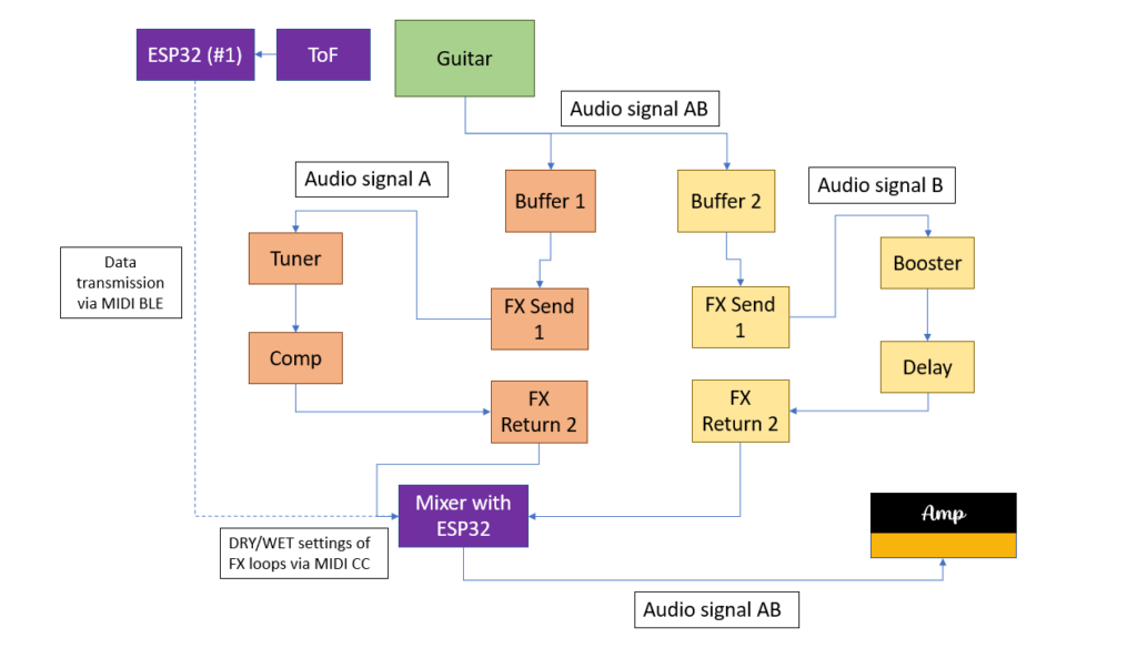
As can be seen in the picture, the idea is to build a kind of MIDI-controlled signal splitter with a built-in mixer. After the splitter, the two audio signals are fed into two different FX loops. One loop would be the “dry” loop with effects that are usually ON; namely tuner, compressor, etc. The other FX loop would be the “wet” loop that contains effects that can be added to the dry signal such as reverb or delay. The ToF sensor and the ESP32 #1 send MIDI CC data to another ESP32 that is contained in the MIDI switch. According to the MIDI CC data received, this ESP32 then controls the DRY/WET ratio of the two FX loops.
Firstly, the described switch was simulated in Pure Data and, of course, worked as expected. However, as the switch involves processing audio signals with the ESP32 just acting as a MIDI CC receiver and controller, the main question was how to switch and split signals using hardware components only. With no prior experience of electrical components and their possibilities, substantial research was done regarding this field. Firstly, the basic functions of classic effect pedals had to be understood. The research yielded some results: it was concluded that in order to switch between to signal chains, a MOSFET or a relay had to be used. Both are electrical components that can act as a switch that can be controlled for example by the output voltage of a microcontroller pin. These suspicions were conveyed to my supervisor, who confirmed them.
Consequently, a relay was purchased at Neuhold. Being new to electrical components, including relays, the first challenge was to get the relay to act as a switch to turn on/off a LED controlled by an Arduino Leonardo. The Arduino Leonardo was chosen because its pins can output 5 Volts which are necessary for the relay to be activated. The pins of the ESP32 can only output 3.3 Volts which is not enough voltage to activate the relay. However, with the Arduino Leonardo, turning the LED on and off using the relay was successfully done. Subsequently, my supervisor provided me with a so-called Darlington transistor which can turn a 3.3 Volts input into a 5 Volts output. Thus, by using the Darlington transistor, the ESP32 with its 3.3 Volt output could now be used to activate the relay. Using two audio jacks, the relay could be successfully used to connect and disconnect a guitar signal played through the circuit.