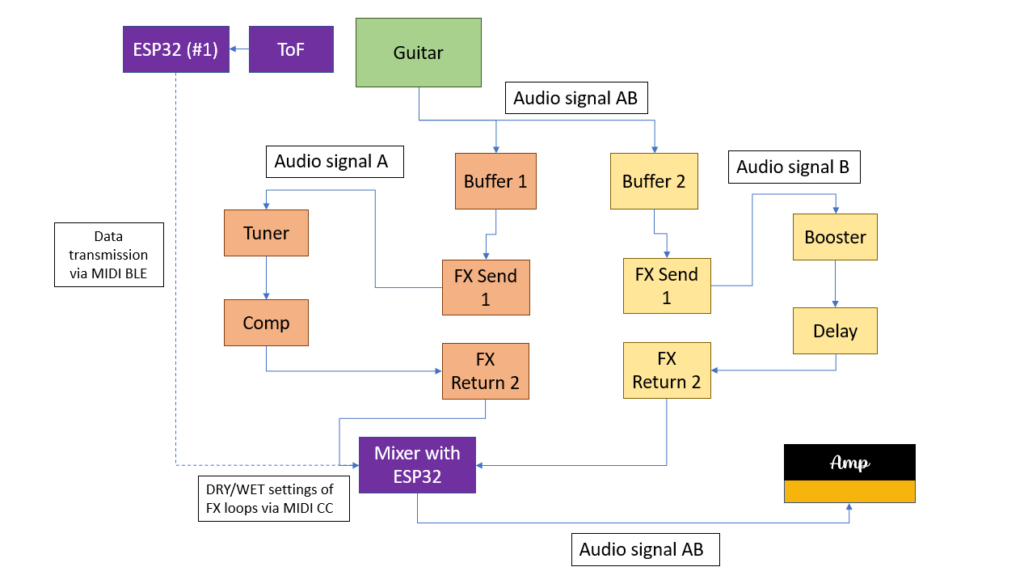
Another thought raised during the meeting was the extension of the project hypotheses. While I primarily focused on not interrupting the player’s natural hand movements, “non-invasive” could also refer to rig compatibility. The setups would therefore fulfill the working hypotheses even more if they could be used in conjuncture with a conventional guitar rig consisting of effect pedals and do not require an additional laptop or other “invasive” measures. Following this train of thought, I came up with a system that enables the guitarist to use his or her own amp and effect pedal chain in conjunction with at least the left hand setup.
As can be seen in the picture, the idea is to build a kind of MIDI-controlled signal splitter with a built-in mixer. After the splitter, the two audio signals are fed into two different FX loops. One loop would be the “dry” loop with effects that are usually ON; namely tuner, compressor, etc. The other FX loop would be the “wet” loop that contains effects that can be added to the dry signal such as reverb or delay. The ToF sensor and the ESP32 #1 send MIDI CC data to another ESP32 that is contained in the MIDI switch. According to the MIDI CC data received, this ESP32 then controls the DRY/WET ratio of the two FX loops.
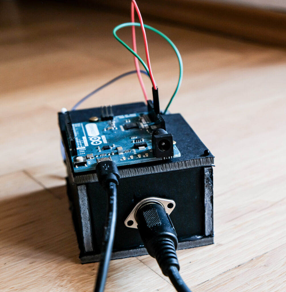
Firstly, the described switch was simulated in Pure Data and, of course, worked as expected. However, as the switch involves processing audio signals with the ESP32 just acting as a MIDI CC receiver and controller, the main question was how to switch and split signals using hardware components only. With no prior experience of electrical components and their possibilities, substantial research was done regarding this field. Firstly, the basic functions of classic effect pedals had to be understood. The research yielded some results: it was concluded that in order to switch between to signal chains, a MOSFET or a relay had to be used. Both are electrical components that can act as a switch that can be controlled for example by the output voltage of a microcontroller pin. These suspicions were conveyed to my supervisor, who confirmed them.
Consequently, a relay was purchased at Neuhold. Being new to electrical components, including relays, the first challenge was to get the relay to act as a switch to turn on/off a LED controlled by an Arduino Leonardo. The Arduino Leonardo was chosen because its pins can output 5 Volts which are necessary for the relay to be activated. The pins of the ESP32 can only output 3.3 Volts which is not enough voltage to activate the relay. However, with the Arduino Leonardo, turning the LED on and off using the relay was successfully done. Subsequently, my supervisor provided me with a so-called Darlington transistor which can turn a 3.3 Volts input into a 5 Volts output. Thus, by using the Darlington transistor, the ESP32 with its 3.3 Volt output could now be used to activate the relay. Using two audio jacks, the relay could be successfully used to connect and disconnect a guitar signal played through the circuit.
The master’s thesis I decided to write about bears the title “Timing-improved Guitar Loop Pedal based on Beat Tracking” and is written by Daniel Rudrich. It was submitted in 2017 at the Institute of Electronic Music and Acoustics (IEM) of the University of Music and Performing Arts Graz (KUG).
I chose the thesis because it documents the development of a tool for guitar which I am planning to do as well for my master’s thesis.
Level of design
Since I am a sound design student myself and no expert/professional (yet) I cannot make a general statement concerning the difficulty or ambition of the project. However, to me and my competences in this field, the project appears to be quite challenging and requires advanced in knowledge in sound and programming.
Degree of innovation
I am a guitarist myself and therefore can relate to the described problem concerning accurate looping. In my opinion, the “timing-improved guitar loop pedal” can be considered quite innovative since I do not know of an existing commercial product that already does the same thing.
Outline of structure
The thesis appears to be very well structured. In the beginning, a brief introduction to the topic at hand is given. Then the problem that the thesis wants to solve is described and, subsequently, the main objective of the thesis (developing an algorithm, which analyses the recorded phrase and supports the musician by aligning the start and stop cues such that the gap is reduced and not perceivable anymore) is stated. Afterwards the development of the mentioned algorithm is documented. Finally, the algorithm is tested through conducting listening tests followed by a conclusion.
Scope of the work
The thesis comprises 76 pages and is therefore quite extensive. To me, the theoretical and practical parts appear well balanced, taking up an equal amount of pages. The theoretical parts also act as a relevant basis for the practical research which was not the case with the master’s thesis I reviewed for the previous task.
Orthography and accuracy
Admittedly, the thesis was not read completely. However, the parts read for this analysis were free of any grammatical or formatting mistakes.
Literature
The bibliography contains 33 citations which is quite an amount for a project documentation. Furthermore, the citations appear to be solely journal articles or books which is also very positive.
Since I was not involved in the project, I cannot say anything regarding the criteria “independence” and “degree of communication”.
Conclusion
All in all, I think this master’s thesis represents a very positive example of “how to do it”. Featuring the development of a challenging practical workpiece and including some theory relevant to the topic, it fulfils the research objective it sets out to solve.
This week I had a meeting with Katharina Groß-Vogt, one of our teachers at IEM concerning supervision of my Master’s thesis. Unfortunately, my current supervisor Marian Weger cannot serve as my supervisor, so I had to find someone else. As I know Kathi from our Sonification lectures and she is an expert in sonic interaction design, I thought that she will be very suitable. Luckily, she liked my project and agreed to supervise my Master’s thesis.
During our meeting, some interesting issues were raised that I had not thought of previously.
#1: The right hand setup currently works with an IMU sensor strapped to the back of the hand. A new idea would be to use another ToF sensor that is attached to the body of the guitar. If angled in the correct way, it could also measure the distance variations of the hand and, thus, achieve a similar effect as the IMU sensor. The advantage of this approach would be that the guitarist must not wear the sensor and can move his or her hand more freely. Additionally, the programming for the ToF sensor is a little bit more straightforward. This new sensor approach was tested. An attachment device was designed to fit the ToF sensor onto the guitar body. Then a code was made that measures the changes in distance if the strumming hand is moved. These changes in movement were then mapped to a Wah-Wah effect in Pure Data. The results are similar to what can be achieved with the IMU sensor. However, the hand must be in a specific position for the effect to work. Furthermore, the code must also be fine-tuned a little bit more. No final decision regarding the sensor of the right hand setup has yet been made, because, at the moment, the development efforts are focused on something else.
#2: In order to ensure usability of the system, it was suggested to involve expert guitarists in the development process sooner than previously planned. In so doing, a more user-centered design process could be achieved that already takes in the guitarists’ insights during the main development phase and not in the 4th semester when the products are already finished. This could prevent the unfortunate scenario in which the guitarists test the finished setups and suggest improvements, but there is no time left to implement the desired ameliorations before the master’s thesis submission deadline. Thus, the plan is to hold interviews with four to five expert guitarists that were shown the video demonstration and informed about the current state of the system. For these interviews, an interview guideline will be developed. The goals will be to:
Receive the current opinion of guitarists concerning the system
Find out more about their live setup and requirements concerning live gear
Gain new insights on how the products could be developed further and become more user-friendly
So far, a first draft of the questionnaire has been created. However, the questions must be reworked. Additionally, expert guitarists must be found. I know two to three guitarists that fit the category that may agree to be interviewed. The search for other guitarists will be conducted at the KUG’s jazz guitar institute.
With the BLE MIDI transmission working rather well, it was decided to move on to finish the programming work of the project. As stated in the goals set for the third semester, the left hand setup will be complemented by an additional threshold-setting knob which enables flexible threshold settings while the right hand setup will have a reset/calibration button added to it. Thus, a potentiometer with matching knob and a button were purchased at Neuhold Elektronik Graz.
As adding the threshold button seemed to be the easier thing to do, it was decided to start with the additions to the left hand setup. Firstly, the basics functions of a potentiometer were researched and a simple code to test the potentiometer and its functionality was written. The potentiometer gives out analog values ranging from 0 to 4095 if operated with 3.3 volts. These values were then divided into nine equal ranges that were matched with nine fret numbers with range 1 going from 0 to 455 for the 1st fret for example. These calculations were then put into code which was also successfully tested. Subsequently, the additional code was added to the main ToF sensor code.
Then another challenge arose: the ESP32 only has one 3.3 Volt pin. However, the ToF sensor and the potentiometer need electricity to work. The first solution found was to connect everything via a breadboard which makes it possible to split the output of the 3.3 Volt pin. This solution works but is not very sleek and thus, not suitable for the final product. Here, some other way will have to be found. Nevertheless, with sensor and potentiometer supplied with power, the code was tested.
Here, an old problem arose. The values fluctuated quite a bit so it was decided to revisit the idea of implementing a code that switches states instead of sending continuous values.
In other words, it was required that if the hand reaches above the set threshold, a MIDI message to turn an effect ON is sent just ONCE and if the hand reaches below the set threshold, a MIDI message to turn the effect OFF is sent just ONCE. If the hand moves but stays above the threshold, no MIDI message is to be sent and if the hand moves but stays under the threshold, no MIDI message is to be sent either.
To make such a code possible, not only the currently incoming fret number had to be known but also the previous fret number so both fret numbers could be compared to each other.
In order to attain the basic logical structure before actually writing the code, four possibilities were discerned:
Prerequisite: Effect is usually ON
Current fret >= threshold && previous fret >= threshold -> do nothing (leave ON)
Current fret >= threshold && previous fret < threshold -> send ON once (turn ON)
Current fret < threshold && previous fret >= threshold -> send OFF once (turn OFF)
Current fret < threshold && previous fret < threshold -> do nothing (leave OFF)
This logical structure was then put into code, but it failed to work at first. As it was hard to debug the code using MIDI messages, it was decided to resort to the old serial monitor and print everything out. Thus, the influence of different conditional operators on the actual output could be monitored very accurately and the code was gradually increased in complexity. Finally, the logical structure mentioned above worked in conjuncture with serial printing. It was then changed to work via MIDI messages, and it also worked successfully. While the code was tested in conjuncture with Cubase, it was not yet tested while actually playing guitar.
After setting the main objectives for the third semester, the first issue that was tackled was the question of how to transmit the data. During the project, quite a few types of data transmissions have been tried out including USB-MIDI, only MIDI and, most recently, OSC.
As already mentioned in blog post #3, data transmission via OSC could be achieved using the ESP32’s WiFi capabilities. This means of communication comes with the definite advantage of being wireless, which was not possible with the MIDI setup from last semester.
However, my supervisor suggested trying out yet another possibility: MIDI via BLE (Bluetooth low energy). So basically, it sends MIDI over Bluetooth. Luckily, the ESP32 also has Bluetooth capabilities so it was possible to start experimenting immediately.
Using the MIDI-BLE library, a code was sketched that could transmit sensor data via MIDI via Bluetooth. Unfortunately, two additional, but free programs are necessary for MIDI BLE to work with Windows. One is called loopMidi which opens a specific MIDI port and the other program is called MIDIberry which lets you route the incoming MIDI signals to the aforementioned MIDI port. This MIDI port can then be selected as a MIDI input source in a DAW (I tested it with Cubase).
Apart from also being wireless, the MIDI BLE data transmission also comes with the additional advantage that it basically sends MIDI signals which work in every DAW almost straightaway while OSC support is not always given or that easy to use. For this very reason, it was decided to drop the OSC possibility for now and focus on MIDI BLE.
In Cubase, one can fully customize the parameter controls via MIDI. So, using Cubase, the “Solo Mode” that was previously written in a Pure Data sketch now works completely without the need for Pure Data since the effects that are turned on or off can now be directly selected in the DAW. This brings the project one more step closer to its completion.
However, while working in Cubase, the current solution does not (yet) work in Reaper for example. This is due to the fact that Reaper only uses the Learn MIDI function to map incoming MIDI CC messages to parameter controls. If two different CC messages are sent at the same time, meant for different effect types, it only recognizes one. It is then not possible to manually input another CC value to control another effect parameter as it is possible in the fully customizable Cubase.
As the two setups should be accessible without too much hassle for most guitarists, it must be established if other DAWs have the possibility of manually mapping MIDI CC values to parameter controls in order to ensure that this method, using MIDI BLE, works for at least the major DAW brands like Pro Tools, Ableton, Logic Pro, etc. if not for Reaper.
On 9th of October the first meeting of the third semester with my supervisor took place. We decided to meet to set the objectives to be reached during the third semester and to determine how the project and the two setups should be developed further.
The first question that arose was whether the focus of the development efforts should be placed on creative advancements of the tonal possibilities of the two setups (for example developing more effects to be controlled by the sensors’ data) or if the focus should be placed on fine-tuning the current setups and developing them into final products.
After some deliberation, it was decided to focus on further developing the existing setups into final products and pass on working on new tonal possibilities. As one of the goals of this project is to test the final setups on guitarists, it was deemed more important that the final setups should also look the part and function properly instead of having endless tonal possibilities but lacking in reliability and looks.
With the main focus of the final product phase set, it was decided to concentrate the development effort on three areas:
Design of setup attachment
Type of data transmission
Software integration
These areas involve the following tasks:
Design of setup attachment
Left hand setup:
3D print cases for ToF sensor and microcontroller ESP32
Develop attachment device that is flexible enough to work on Fender AND Gibson headstock shapes
Extra knob for fret threshold setting
Extra knob for fine-tuning fret detection (?)
Determine power supply -> battery
Right hand setup:
3D print cases for IMU sensor and microcontroller ESP32
Extra calibration button
Develop attachment -> use snap fasteners to clip sensor + microcontroller on
Determine power supply -> battery
Strong cover cable to connect sensor and microcontroller
Type of data transmission
Via OSC (current solution)
Pros: wireless, already works
Cons: integration in DAW more complicated (maybe different for every DAW)
Via Bluetooth + MIDI (BLE) (probably best solution)
Pros: integration in DAW probably easier with “Learn MIDI”, ESP32 has Bluetooth
Cons: does not work yet, fast enough? USB dongle necessary?
Via radio transmission (?)
Software integration
Goal: make setups useable within DAW
As already touched upon in previous blog posts, some experiments were done using the Camomile VST software. While achieving some success, it was still decided to abandon the idea of working with Camomile. On one hand, it was not possible to solve the issue of the effect not affecting the recorded signal. On the other hand, the Camomile environment was deemed impractical for the left hand setup.
Instead, the development efforts will focus on OSC or BLE + MIDI. Especially the latter solution appears to be promising because one could use the MIDI learn function that comes with practically any DAW that allows the user to use any plugins and customize controllable parameters within the DAW.
With these goals and focus areas set, the third project phase is really about to start. The first issue that will be tackled is determining the type of data transmission as well as the software integration.
With both setups working via OSC, it was time to focus on another goal of the third project phase: the final software implementation. As stated before, the aim of this project is to further advance the sonic range of the electric guitar without impairing the guitar player’s natural playing. Although this statement mainly includes the natural playing style and associated hand movements of the player, its meaning could also be expanded to usability and how well the two setups can be integrated into the usual signal chain of the average guitar player.
The standard guitar signal chain is probably as follows:
Guitar into effect pedals into amp to microphone or interface
As both setups require a computer, implementing the setups into this signal chain will not be possible. However, a lot of guitarists nowadays will play straight into an interface + DAW or go from an amp into an interface + DAW. Hence, if the software of the project could be integrated into a DAW, it could be considered quite user-friendly for guitarists.
And here Camomile comes into play. Camomile is an audio plugin with Pure Data embedded, used to control patches inside a large set of digital audio workstations – as long as they support VST3 or Audio Unit formats. (1) It free, open-source and cross-platform and was developed by Pierre Guillot.
The plan is to convert the current Pure Data patches into VST plugins that can then be used in any DAW, making them more accessible and prone to be used by guitarists.
The left hand setup with its usage of third-party plugins seems not as suited at the moment, however, ways will be found to implement it as well. Nevertheless, for reasons of simplicity, it was decided to start with the right hand setup and try to make it work together with Camomile.
Luckily, Camomile comes with a WikiPage that explains how to generate plugins and also how to make new plugins. As far as I understood it, Camomile is sort of a platform that facilitates and enables communication between the Pure Data patch and DAW. In order to generate a VST plugin, one needs a folder that contains the Pure Data patch and sub-patches, the Camomile VST Plugin-File (instrument or effect), an info sketch in txt format and specific Pure Data sketches that facilitate communication between patch and DAW.
Within the text file, the parameters of the plugin, the in- and outputs and other factors need to be specified. For example, for the Wah-Wah effect patch, the following text was written:
The first parameter is the center frequency of the Wah-Wah and the second on is the ON/OFF switch for the OSC reception.
Additionally, one must add the specifically written param.get, param.set and param.change sketches to one’s own sketch in order to ensure communication between patch and DAW.
Without going too much into detail, it was possible to generate a Wah-Wah plugin that can be opened in the DAW Cubase. The center frequency can be controlled via OSC with data coming from the IMU sensor. Furthermore, the parameters center frequency and OSC ON/OFF can be automated manually and in Write-Mode within the DAW.
However, there is one problem: While the center frequency can be automated when moving the slider while in Write-Mode or drawing in automation curves, it cannot be automated from the OSC data alone. Similarly, the Wah-Wah affects the tone of a guitar when played live, however, it does not affect it anymore after recording the guitar. These two issues are, of course, linked but so far, no solution could be found. On the upside, while searching for a solution, the Camomile plugin and its workings were understood much better.
Nevertheless, I am confident that this problem will be solved in the near future.
As stated in blog post #1, basic OSC transmission capabilities were achieved and thus, the IMU sensor’s data could now be transmitted via OSC to control the parameters of a Wah-Wah effect. The next step was to test this setup in conjuncture with real guitar playing. However, it was decided that a new attachment device for the ESP32 microcontroller was needed.
Prior to using OSC, the right hand setup used MIDI to transmit the sensor data from sensor + microcontroller to Pure Data. The IMU sensor was attached to the microcontroller (an Arduino Leonardo) via a long cable and the microcontroller itself was fitted onto a small housing with a MIDI jack attached to it.
With the ESP32 microcontroller now working wirelessly over OSC, there was no further need for the housing and the long cable. It was instead decided to fit the ESP32 on the right forearm of the guitar player with only a short cable connecting it to the IMU sensor which was still fitted onto the wristwatch. However, it proved difficult to find a way of attaching the sensor to the uneven surface of a human forearm. After some pondering of the issue, the idea was born to use an old sock to wrap around the arm onto which the ESP32, wrapped into a small bag of fabric, could subsequently be sewn. It must be stated that this means of attachment is not yet worthy of the name “final product” and another solution must be found. Nevertheless, for testing purposes the device sufficed. The Wah-Wah effect could be tested using OSC as a means of transmission and it worked as expected. Thus, it can be concluded that the right hand setup now works wirelessly which brings it closer to its ultimate goal of not impairing the guitarist’s natural playing style while still adding another dimension of sound to the guitar.
With the right hand setup working so well, it was time to transform the left hand setup in the same fashion and make it work wirelessly. Having established the basic OSC principles while working on the right hand setup, it was simply a matter of combining the original code made for the ToF sensor with the OSC code. The “new” left hand setup was then immediately tested using the previously made “Solo Mode” Pure Data patch and a guitar. As it was the case with the right hand setup, the wireless left hand setup seemed to work equally well as the MIDI-based setup.
While the transmission of data now works wirelessly via OSC, both setups still require to connect the respective sensors (IMU and ToF sensors) to the ESP32 microcontroller. With both sensor being relatively wide apart from each other, it is likely that two microcontrollers, one for each hand’s setup must be used for the final product.
Hello and welcome back to my GPRO project as I like to call it. We are now entering the third semester already during which the prototype setups developed during the previous semester will be completed to final products. Instead of overthinking my next steps and planning too much ahead, I decided to jump right back in and continue where I stood at the end of the second semester.
As noted in the documentation and presentation of the second phase, both setups, in particular the right hand setup would benefit from being wireless, with no cables obstructing the guitar player’s movements. Hence, this was the first issue tackled. Although there exist several possibilities to send data wirelessly, it was quickly decided to try out OSC (open sound control) which works over WIFI.
Open Sound Control (OSC) is an open, transport-independent, message-based protocol developed for communication among computers, sound synthesizers, and other multimedia devices. OSC messages are transported across the internet and within local subnets using UDP/IP and Ethernet. Additionally, OSC is sometimes used as an alternative to the 1983 MIDI standard.
This decision was taken among other reasons because the author was provided with an ESP32 microcontroller at the end of the second semester by his supervisor which already has WIFI capabilities on board. As the name already suggests, the ESP32 is not an Arduino product, however, it still can be programmed using the Arduino IDE after conducting a manual implementation process. With only a few difficulties, said process was completed and the ESP32 ready to be programmed.
The first step was to write an Arduino sketch which connects the ESP32 to the local WIFI network of the author in order to be able to send OSC messages. Using the OSC library for Arduino, such a code was achieved in a rather short time. Furthermore, the OSC library also contained a very useful example sketch to send OSC messages which served as a great learning tool to understand how OSC messaging works. In order to test the OSC messaging function, a Pure Data patch was made which uses the “netreceive” and “oscparse” objects among others to receive OSC messages coming in from a predefined port. The “netreceive” objects allows Pure Data to listen to a specific port, in this case 8000. In the Arduino sketch the port 8000 was defined as the outport from which OSC messages are sent. As a result, OSC messages could now be sent from the ESP32 via WIFI to Pure Data.
After achieving basic OSC messaging capabilities, the subsequent step was to merge the original sketch for the right hand setup, containing the code to access the IMU data readings, with the new OSC messaging method. On the other hand, the Pure Data patch from the second semester which is set up to receive the y-value of the orientation data from the IMU sensor to control a Wah-Wah effect was updated was well. Instead of receiving the orientation data as MIDI input, it now receives the orientation data via OSC, using the objects mentioned above.
After establishing the pin layout of the ESP32, the IMU sensor (still attached to the wrist watch device) could be connected to the microcontroller and data transmission from the ESP32 to Pure Data was successful. Latency seemed to be comparable to that of MIDI. With basic OSC transmission working, it is time to test the new setup it in conjuncture with real guitar playing.
In this chapter, the project’s progress, made during the second semester, will be evaluated and successful as well as failed outcomes will be discussed. The evaluation will be based on the goals that were set out to be fulfilled during the second phase of the project.
Goal Number
Description
Goal 1
Determine and acquire necessary equipment
Goal 2
Determine ideal placement of sensors and microcontrollers on guitar neck and pick/right hand and install them accordingly
Goal 3
Program microcontrollers to pick up the movements of the fretting and picking hands using the Integrated Development Environment (IDE) by Arduino
Goal 4
Program a Pure Data patch that handles the incoming data and transforms it to useable parameters to trigger effects
Goal 5
Either program custom effects in Pure Data or integrate Pure Data in a DAW to trigger commercial effect plug-ins
Goal 6
Determine suitable effects and parameters to be triggered by the movements of the fretting and picking hands
As far as the first goal is concerned, it can be stated that this task was accomplished. As outlined above, the necessary and suitable equipment for both the left and right hand setups was determined. This was achieved by thoroughly researching potentially suitable components and submitting them to tests in order to identify the best solution possible.
With regards to the choice of a microcontroller, the Arduino Leonardo was chosen over the Arduino UNO due to its built-in USB communication and USB MIDI device capabilities. Albeit the Leonardo being rather big and unwieldy, it was decided to stick with it during the experimental phase on simplicity grounds since it could be borrowed from the FH JOANNEUM. However, it is likely that a smaller microcontroller with similar performance such as an Arduino Micro will be used for the final setups in project phase three.
Regarding the sensor for the left hand setup, diligent research and a direct performance comparison lead to the decision to use a time-of-flight sensor to pinpoint the position of the guitarist’s hand along the neck instead of the initially planned ultrasonic sensor. After evaluating the specifications of several ToF sensors, the sensor of the type VL53L1X was finally chosen.
For the right hand setup on the other hand, a suitable IMU sensor was found rather quickly. Although an MPU9250 was briefly considered and used during an initial Arduino library test, it was then dropped for a BNO055 sensor, following the recommendation of the author’s supervisor.
Of course, next to these main components, other equipment including cables, breadboard, electronic components, etc. were acquired.
All in all, this goal has been largely fulfilled with some improvements possible in the third phase of the project.
As outlined above, the usual positions of the fretting hand have been determined and subsequently analyzed. This analysis led to the conclusion that, unfortunately, the posture and the exposed reflection area of the fretting hand vary a lot depending on what is played, with major differences between playing barre chords and single notes for instance. These inconsistencies in hand posture were and still are a major constraint to the left hand setup and its flawless implementation into the natural playing style of a guitarist.
As far as the ideal place and installation of the sensors is concerned, a lot of progress was made with regards to the left hand setup. Based on the afore-mentioned analysis of the hand posture, several attachment devices were made for the ultrasonic as well as the ToF sensors and, subsequently, compared. One position in particular (IMAGE) proved to be better than the others, albeit being not perfect. The position chosen works best for barre chords as well as the Solo Mode application.
Regarding the attachment device of the right hand setup, there is definite room for improvement. The wristwatch solution was sufficient for the experimental phase and proved that placing the sensor on top of the back of the hand serves to get useful sensor data. However, it is unsuitable for the final product. While a wireless solution is optional for the left hand setup, the right hand setup would certainly benefit from the lack of cables. It would enable an even more natural playing of the guitar.
Here, definite progress was made, especially with the left hand setup. With no prior experience in programming the learning curve was quite steep, and a lot of time had to be dedicated just to learn basic coding techniques.
Regarding the left hand setup, Arduino sketches were made firstly for the ultrasonic sensor and, subsequently, for the time-of-flight sensor when the former proved to be unsuitable. In addition to code needed to access the basic sensor data, the mathematical relationship of the guitar fret spacings was established, fret ranges were determined and finally implemented in the code. Next to absolute distance measurements, detecting the fret numbers is possible up to the ninth fret which already enables applications such as the Solo Mode.
The code for the right hand setup on the other hand is not yet as advanced mainly due to time constraints. Using a library, orientation, acceleration, and calibration data could be obtained from the IMU sensor and transmitted to Pure Data via MIDI. The y value from the orientation data is the only data so far that is suitable for further use to control effect parameters of a Wah Wah effect. Here, more variety in data usage would be desirable.
Lastly, different data transmission techniques were tested and evaluated. A lot of time was spent with first MIDI USB libraries and then MIDI only libraries with transmission suffering from a lot if lag initially. Serial port communication proved to be the first viable solution, fast enough to control effect parameters. Finally, the latency problems of MIDI could be eliminated. The current setups work via MIDI communication using a MIDI cable. For the third phase, a wireless means of data transmission would be desirable – especially for the right hand setup.
This goal was achieved to a large extent. Albeit initially working only with great latency issues, making a patch that receives MIDI data and is able to use it for further processing was achieved rather easily. The interim solution, serial port communication, took some more research but once the basic method was discovered, its application was straightforward. For the left hand setup, the incoming fret numbers can be either used directly to control effect parameters or, using the “moses” object for instance, a fret threshold can be set to make an ON/OFF switch. The patch for the right hand setup is very similar to that of its counterpart and effect parameters can be controlled.
As far as goal 5 is concerned, mixed results were achieved. Working with the digital audio workstation (DAW) Steinberg Cubase Pro 11 proved to be more difficult than previously anticipated and, consequently, it was decided to work with Pure Data only during the experimental phase. Nevertheless, in order to ensure a seamless integration into the guitarist’s natural workflow, a DAW integration of the final product is desirable. Thus, it will be tried to accomplish this in the third phase of the project.
Regarding the decision between using self-made effects or third-party plugins, both approaches were tested. The first patch contained a self-made delay and overdrive/distortion effect which proved to be useful for the first test but had definite shortcomings tonal quality-wise. Thus, the patches from then on used the object “vstplugin~” to implement third-party plugins in the Pure Data environment. The exception is the Wah-Wah effect for the right hand setup which is self-made and works well.
With a stable data transmission between Arduino and Pure Data achieved at a relatively late stage of the semester, this goal could not be fully achieved. Tone experiments involving several effects and their parameters were conducted. For the Solo Mode application of the left hand setup, an amplifier, reverb and delay were tested. Less tonal experimenting was done with the right hand setup: three effects tremolo, phaser and Wah Wah were tested with only the latter representing a reasonable effect to be controlled by the right hand setup.
It is evident, that only the surface has been scratched so far and much more in-depth research and experimenting in both setups will be needed to really provide practical applications for extending the range of possible guitar sounds.
In conclusion, it can be stated that all tasks set to be done during the second phase of the project have been approached and tackled with the majority of goals at least partially achieved. Additionally, setup compatibility with working hypotheses 1 and 2 was consistently ensured, with all effects working so far not invading the usual way people play guitar. As stated in the Exposé and in chapter 4 of this documentation, the overall aim of the second phase was to develop working setups that are sufficiently reliable and allow for further practical research regarding suitable effects, playability and performability. While the left and right hand setups are far from being a final product or ready to be tested by other guitarists, the second, experimental phase yielded a lot of progress. Overall, it can be affirmed that the left and right hand setups, albeit having shortcomings in some areas, are advanced enough to serve as a base for further practical research in the third semester.