Right hand setup attachment

While the attachment device for the left hand setup is largely finished, the final attachment for the right hand setup must still be built. The basic idea follows a prototype that has already been built. This prototype involves textile straps onto which the IMU sensor, the ESP32 and the battery supply are sewn. Unfortunately, this version resembled bandages and still has room for improvement so it was decided to build another, better version.

Firstly, the strap for the hand that secures the IMU sensor to the back of the hand was created. Therefore, a black rubber/textile band was sewn to a shape to make it wearable in a way that places the sensor in the correct position while ensuring that it does not interfere to much with the guitar playing motions of the right hand. Velcro was added to the rubber strap in specific places so it can be easily put on and fastened as desired.

Another challenge that arose during the development of said new attachment device, is that the rubber strap places the sensor in a different position than it was previously. As the sensor is an IMU sensor, its position is quite significant. In the new position, the values read by the sensor do not fit the mapping previously made when the sensor was fitted onto the wrist watch. Accordingly, the values needed to be re-mapped.

With the sensor in its new position, an electric guitar was played with the right hand performing typical strumming movements. Then, the orientation data in x, y and z direction coming in the Arduino IDE serial monitor was copied into a Word document and the values subsequently copied into an Excel sheet. There the values were put into a graph. The graph of the y values seemed to represent the strumming movements in the most accurate way. Initially, the x values appeared to be useful as well but when restarting the IMU sensor code, the x values suddenly changed a lot, and the values were in a totally different range. Consequently, the y values which were more consistent were chosen as the values to be used.

To further test the y values’ suitability, the old Pure Data sketch containing the Wah Wah effect was revisited and the y values used to control the effect. This worked fine. However, one issue remains: a way must be figured out how to use the IMU values as an expression pedal to control guitar effect pedals with an expression pedal input.

While working on the arm strap onto which the ESP32 will be fixed, another issue arose that was already mentioned in the Blog post #12: the battery supply. The AA battery pack proved to be too unwieldy to be worn on the arm so another possibility had to be found. The current solution is to simply use a small power bank to power the ESP32 of the right hand setup and possibly the one of the left hand setup as well. According to some articles on the Internet it is not the most efficient solution to power an ESP32 but considering the slight time pressure, this solution will be adopted for now.
Battery supply musings

Another issue raised in the meeting with the project’s supervisor was the energy supply for the left hand, right hand setups and central hardware unit. The central hardware unit must supply power for the splitter and mixer and, additionally, for the ESP32-CU (central unit). The solution the splitter and the mixer was quite straightforward: both need a 9 volt power supply to function and the typical guitar effect pedal is also supplied by a 9 Volt battery. Accordingly, a 9 Volt battery or power input will be used to power most of the central hardware unit.

The greater challenge was to find a suitable power supply for the ESP32s. Using a 9 Volt battery would have been a practicable and comparatively small solution but as an ESP32 only needs 3.3 Volts a 9 Volt battery would also be a very inefficient solution. An Internet research session yielded two better possibilities: using 3 AA batteries or using one 18650 battery. The latter are lithium-ion rechargeable batteries with a voltage of 3.7 Volts. They are actually an ideal solution but are a bit dangerous when carelessly used. That is why the solution using 3 AA batteries was looked at first. At Neuhold a battery case for 4 AA batteries was obtained. Consequently, one battery slot had to be connected by a cable soldered to the contacts. To start off, the battery pack was used to power a LED, and this worked out fine. Next, an ESP32 connected to a ToF sensor was tested. The ESP32 sent the sensor data to the computer using MIDI-BLE so the USB-cable could be disconnected to see if it was really the battery pack that was powering the microcontroller. This worked as well. This made the 3 AA battery pack a suitable option to power the ESP32s in this project. The big disadvantage of using the AA battery pack is its size and unwieldiness. While this is not an issue for the ESP32-CU, it is a great problem for the right hand setup for example where the whole setup should basically fit into the back of the hand and the forearm without interfering too much with the actual guitar playing. This is why using a 18650 battery is re-considered, at least for the right hand setup.

When using the ESP32s on battery supply, it was decided that it would be a good feature to have some kind of battery monitoring, indicating a low battery status to the user. Luckily, there was a good tutorial online explaining how to get an ESP32 to monitor its own battery level. It appeared to be fairly straightforward, involving just two 10k resistors and a few lines of code. The idea was to flash a LED if the battery voltage dropped to a certain level, just like the principle of the power supply of electro-acoustic guitars where a low battery is also indicated by a red LED. Unfortunately, all (or just my) ESP32s seem to have a problem with the analogRead() function and the monitoring did not work as expected. This issue is something to be solved in the future.

Sources:

Everything You Need to Know About the 18650 Battery (commonsensehome.com)

Getting the ESP32 to monitor its own battery level – XTronical

ESP-NOW – yet another way to communicate

After achieving the major goal of finding a final-product-worthy attachment solution of the left hand setup, it was decided to find out how to communicate between two ESP32s. Although the splitter and the mixer were still not working properly, the question of how to communicate between two (or more) ESP32s was still an important issue to solve. The manner of communication at this time of the project was MIDI-BLE so accordingly, solutions involving MIDI-BLE were investigated first. After doing some research, it was determined that communication between two ESP32s was possible via MIDI-BLE but quite complicated. However, another, entirely different option presented itself: apparently there is a way to communicate between several ESP32s using Espressif’s (inventor of ESP32s) native communication protocol called ESP-NOW.

According to the Espressif website, ESP-NOW is yet another protocol developed by Espressif, which enables multiple devices to communicate with one another without using Wi-Fi. The protocol is similar to the low-power 2.4GHz wireless connectivity that is often deployed in wireless mouses. So, the pairing between devices is needed prior to their communication. After the pairing is done, the connection is secure and peer-to-peer, with no handshake being required. Its features include:

  • Quick and automatic connectivity once two or more devices have been paired
  • Fast transmission speed
  • Low power-consumption
  • Improved Range and Reception

These qualities make it ideal for the GPRO project.

Following an online tutorial, it was quickly determined how to connect two ESP32 boards and establish a two-way communication between them. As always, a prototype sketch was made, focusing on the basic functionality of the ESP-NOW protocol. After basic communication capabilities had been achieved, ESP-NOW was integrated into the existing code for the left hand setup and the ToF sensor. The test was successful: now, ON/OFF commands based on the fret detected can be sent via ESP-NOW from the ESP32 connected to the sensor to the ESP32 simulating the future central hardware unit. It was noted that the transmission rate is indeed very fast and appears to be greater than the one of MIDI-BLE.

In a meeting prior to Christmas, the project’s supervisor suggested computing the frets and sending corresponding ON/OFF commands could be done by the ESP32 in the central hardware unit (ESP32-CU) instead of the ESP32 at the headstock (ESP32-HS). This would eliminate the need for the ESP32-CU to send the selected threshold to the ESP32-HS and a one-way communication would be sufficient. This will be done.

The ESP-NOW protocol must still be implemented in the code for the right hand setup and IMU sensor. However, it will likely be just as suitable for the right hand setup as it was for the left hand setup. The code for the right hand setup must still be changed anyways because by using the new and final attachment device for the right hand setup, the IMU sensor will be placed in a different position than before, resulting in the need to adapt the sensor readings. But more of this, in the next blog post…

Sources:

ESP-Now Overview | Espressif Systems

ESP-NOW: Espressif’s Wireless Communication Protocol | Espressif Systems

Getting Started with ESP-NOW (ESP32 with Arduino IDE) | Random Nerd Tutorials

Mixer troubles and attachment progress

As mentioned in the post before, jumper wires were soldered to all audio jacks in order to test the splitter and mixer by simulating two FX loops. As stereo jacks had been bought, it was important to solder the wires to the correct parts on the audio jacks to make them work with mono TS guitar cables. With the audio jacks sorted, the FX loops were then simulated by leaving one signal dry and putting a booster in the second signal chain. If the signal got louder, the FX loops should work as expected. Unfortunately, the circuits were not perfect yet. While both circuits, that of the splitter and that of the mixer seem to work fine on their own, they produced a very loud humming noise leaving the guitar signal barely audible. Sometimes it did not work at all.

Before Christmas, the project’s supervisor was consulted, and he provided a picture of the same mixer circuit that he recreated for some other project. Using this picture as a guidance, the mixer circuit was tackled again. Additionally, a bigger breadboard was bought to better accommodate the circuit. Nevertheless, the mixer’s performance did not improve a lot. While it seems to work, the humming noise is still very present making it unsuitable for further use within the project. As of now, the splitter/mixer components of the hardware switch are not working and a solution for this major problem must be found.

Another challenge was to find a solution for the attachment of the ToF sensor of the left hand setup. As already mentioned, the attachment device should be flexible enough to fit onto both, Fender headstocks as well as Gibson headstocks, the two most common headstock shapes in the guitar world. The first idea was to use a swan-neck and some type of table clamp and said parts were ordered. Upon delivery however, it was clear that the table clamp was way too big and heavy for the comparatively fragile guitar headstock. Additionally, the swan-neck proved to be too short and too inflexible so the sensor could not be positioned correctly. Afterwards, a swan-neck lamp by IKEA was tested. It was more lightweight and flexible enough to position the sensor correctly. However, it was not stable enough and changed its alignment with every move of the guitar. This, of course, made rendered it impossible to be used as an attachment device. There was more luck to be found with the third possible solution, a device consisting of a clamp and a semi-flexible arm with joints originally made to hold a GoPro. The clamp was small enough to fit onto guitar headstocks. The arm was flexible enough to position the sensor in the way required for a Fender headstock and a Gibson-type headstock. At the same time, it proved sturdy enough to hold its position while moving. A small setback happened that could be sorted out quickly: for testing a different (but very similar) ToF sensor of the type VL53L0X was used that could not detect the frets as accurately as the original ToF sensor. Worried that the new attachment device required major changes in the Arduino code of the ToF sensor, the original VL53L1X sensor was used. Luckily, it worked fine and could detect the frets as accurately as with the old attachment device. Just to be sure, another VL53L1X sensor was ordered as a back-up.

ProMa | Critical Evaluation of a Master’s Thesis

Evaluation of the master’s thesis: From live to interactive electronics by Artemi – Maria Gioti, written in 2015.

Level of Design

The thesis was handed in at the University of Arts in Graz, which, like most universities, has a rather specific and strict style that theses need to adhere to. In the case of the University of Arts in Graz, this means an estimated font size of 11 and double line spacing on a white A4 sheets. The whole thesis is (even in its PDF-version) in black and white without a single spot of color to be found.

This of course makes it rather difficult to evaluate the design of this thesis – knowing that there was basically no design of choice involved. However, I still find this very minimal and “scientific” style to be rather pleasant, as long as the work sticks to a standard scientific structure, too.

Degree of Innovation

The thesis topic seems very innovative – live performance in symbiosis with software agents is a topic that strives to explore new ground on various levels: The technical background. the musical aspects, as well as the whole artistic perspective of performative arts.

Independence

I do not feel like I am in a position to evaluate the independence of this thesis. However, since the topic seems to stem from very individual interests, I am confident that the thesis was conducted with at least sufficient independence.

Outline and Structure

While the outline seems generally logical to me, I was heavily missing an introduction. The first part of the thesis is structured into background and terminology of the topic, which is an interesting and refreshing approach considering the field of performative arts. The second part talks about Gioti’s work, the system that she performed live with. While this becomes clear when reading, I still would have preferred to get to know about the approach to the structure within an introductory chapter. It also counts to say that the thesis is very short, with 26 pages in total. If it was longer, the outline might have been even more confusing and would have definitely needed structural guidance.

Degree of Communication

The author communicates very professionally in English, with complex enough sentences, that are still not too difficult to read. However, I feel like there is too much of an avoidance of writing first person statements and in turn too much passive voice, which are leading to some confusion about subjects in some sentences in my opinion.

Scope of the Work

While the topic seems very interesting, the thesis clearly turned out rather short. The theoretical first part is very general and also on point, and while there does not seem to be missing anything substantial, it also does not seem very specific – which is something I would usually expect from a master’s thesis.

The second part is well written and crisp, but extensive enough. This makes the first part slightly seem like a mandatory small effort contribution to the thesis to become complete.

Orthography and Accuracy

The thesis looks clean and well written. I did not come across any spelling mistakes or typos, however, there is a wrong page number stated in the table of contents.

Literature

For the small amount of pages, there seems to be an okay amount of references. Unfortunately a lot of the references are very old. I would estimate almost half were published more than 15 years before this thesis was written.

Gioti, A. From live to interactive electronics. Masterarbeit, 2015.

MIDI switch two

While switching between two FX loops was now theoretically possible, a DRY/WET control still needed to be implemented. My supervisor suggested using the schematics of a splitter and a mixer found on the Internet. As the name already suggests, the splitter splits the incoming guitar signal into two separate signals. These signals each have their own FX loop and go through different effects. Then, they are reconciled in the mixer, where the DRY/WET ratio of the two signals is set and they are both unified into one signal that is then sent on to the amp. The unfortunate part was that by using this method, no bypass switch using relay, MOSFET or Darlington transistor was necessary anymore. Nevertheless, important things have been learnt and the research and tests than were not completely for nothing.

Having never worked with schematics before, basic knowledge about reading and understanding schematics and the components involved had to be acquired. Then, it was decided to start of with the splitter and the necessary parts were bought at Neuhold. Luckily, a sound designer colleague could help me out with a 1uf Elko transistor which was not available at Neuhold. With all parts gathered, it was tried to assemble the circuit. The circuit was assembled on a breadboard. The advantage here is that the parts are not soldered and, thus, fixed in their position. Consequently, mistakes can be more easily remedied. Following the instructions, the circuit was built. To great surprise, it seemed to work. The circuit was tested using two guitar amps and a guitar. The signal of the guitar could be split up to go into both amps at the same time. Thus, the test was deemed successful. However, the two split-up signals appeared to be weaker than the one signal. According to my supervisor, this could be because of the use of different transistors than recommended in the schematic. It will be tried to acquire the correct transistors in order to remedy this problem.

With the splitter working, the mixer had to be built. The mixer posed a greater challenge. Fortunately, my supervisor provided me with the parts necessary. The building of the circuit, however, proved to be quite complicated. The schematic was firstly recreated in the DIY layout creator that lets you create circuits in a graphical way. With the circuit drawn like that, the actual circuit was built on a breadboard. It was testes by plugging in two guitars at the inputs and the output was plugged into an amp. The test was successful: Both guitar signals went through the circuit and into the amp. Furthermore, their individual volume levels could be adjusted using the potentiometers at the input. Nevertheless, I am not entirely sure that everything was done correctly – it just seems too good to be true.

Unfortunately, both parts, splitter and mixer, could not be tested in conjuncture due to the lack of two (!) crocodile clamps that are used to connect the audio jacks to their inputs and outputs. Thus, I cannot simulate the whole signal flow and experiment with the two FX loops yet. However, I have decided to solder cables to the remaining audio jack to be able to test my setup.

MIDI switch idea

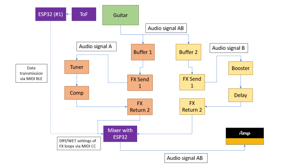
Another thought raised during the meeting was the extension of the project hypotheses. While I primarily focused on not interrupting the player’s natural hand movements, “non-invasive” could also refer to rig compatibility. The setups would therefore fulfill the working hypotheses even more if they could be used in conjuncture with a conventional guitar rig consisting of effect pedals and do not require an additional laptop or other “invasive” measures. Following this train of thought, I came up with a system that enables the guitarist to use his or her own amp and effect pedal chain in conjunction with at least the left hand setup.

As can be seen in the picture, the idea is to build a kind of MIDI-controlled signal splitter with a built-in mixer. After the splitter, the two audio signals are fed into two different FX loops. One loop would be the “dry” loop with effects that are usually ON; namely tuner, compressor, etc. The other FX loop would be the “wet” loop that contains effects that can be added to the dry signal such as reverb or delay. The ToF sensor and the ESP32 #1 send MIDI CC data to another ESP32 that is contained in the MIDI switch. According to the MIDI CC data received, this ESP32 then controls the DRY/WET ratio of the two FX loops.

Firstly, the described switch was simulated in Pure Data and, of course, worked as expected. However, as the switch involves processing audio signals with the ESP32 just acting as a MIDI CC receiver and controller, the main question was how to switch and split signals using hardware components only. With no prior experience of electrical components and their possibilities, substantial research was done regarding this field. Firstly, the basic functions of classic effect pedals had to be understood. The research yielded some results: it was concluded that in order to switch between to signal chains, a MOSFET or a relay had to be used. Both are electrical components that can act as a switch that can be controlled for example by the output voltage of a microcontroller pin. These suspicions were conveyed to my supervisor, who confirmed them.

Consequently, a relay was purchased at Neuhold. Being new to electrical components, including relays, the first challenge was to get the relay to act as a switch to turn on/off a LED controlled by an Arduino Leonardo. The Arduino Leonardo was chosen because its pins can output 5 Volts which are necessary for the relay to be activated. The pins of the ESP32 can only output 3.3 Volts which is not enough voltage to activate the relay. However, with the Arduino Leonardo, turning the LED on and off using the relay was successfully done. Subsequently, my supervisor provided me with a so-called Darlington transistor which can turn a 3.3 Volts input into a 5 Volts output. Thus, by using the Darlington transistor, the ESP32 with its 3.3 Volt output could now be used to activate the relay. Using two audio jacks, the relay could be successfully used to connect and disconnect a guitar signal played through the circuit.

Kritische Bewertung einer Masterarbeit

Aufgabe III Erstellung eines Blogeintrages

The master’s thesis I decided to write about bears the title “Timing-improved Guitar Loop Pedal based on Beat Tracking” and is written by Daniel Rudrich. It was submitted in 2017 at the Institute of Electronic Music and Acoustics (IEM) of the University of Music and Performing Arts Graz (KUG).

I chose the thesis because it documents the development of a tool for guitar which I am planning to do as well for my master’s thesis.

Level of design

Since I am a sound design student myself and no expert/professional (yet) I cannot make a general statement concerning the difficulty or ambition of the project. However, to me and my competences in this field, the project appears to be quite challenging and requires advanced in knowledge in sound and programming.

Degree of innovation

I am a guitarist myself and therefore can relate to the described problem concerning accurate looping. In my opinion, the “timing-improved guitar loop pedal” can be considered quite innovative since I do not know of an existing commercial product that already does the same thing.

Outline of structure

The thesis appears to be very well structured. In the beginning, a brief introduction to the topic at hand is given. Then the problem that the thesis wants to solve is described and, subsequently, the main objective of the thesis (developing an algorithm, which analyses the recorded phrase and supports the musician by aligning the start and stop cues such that the gap is reduced and not perceivable anymore) is stated. Afterwards the development of the mentioned algorithm is documented. Finally, the algorithm is tested through conducting listening tests followed by a conclusion.

Scope of the work

The thesis comprises 76 pages and is therefore quite extensive. To me, the theoretical and practical parts appear well balanced, taking up an equal amount of pages. The theoretical parts also act as a relevant basis for the practical research which was not the case with the master’s thesis I reviewed for the previous task.

Orthography and accuracy

Admittedly, the thesis was not read completely. However, the parts read for this analysis were free of any grammatical or formatting mistakes.

Literature

The bibliography contains 33 citations which is quite an amount for a project documentation. Furthermore, the citations appear to be solely journal articles or books which is also very positive.

Since I was not involved in the project, I cannot say anything regarding the criteria “independence” and “degree of communication”.

Conclusion

All in all, I think this master’s thesis represents a very positive example of “how to do it”. Featuring the development of a challenging practical workpiece and including some theory relevant to the topic, it fulfils the research objective it sets out to solve.

Meeting with Master’s thesis supervisor

This week I had a meeting with Katharina Groß-Vogt, one of our teachers at IEM concerning supervision of my Master’s thesis. Unfortunately, my current supervisor Marian Weger cannot serve as my supervisor, so I had to find someone else. As I know Kathi from our Sonification lectures and she is an expert in sonic interaction design, I thought that she will be very suitable. Luckily, she liked my project and agreed to supervise my Master’s thesis.

During our meeting, some interesting issues were raised that I had not thought of previously.

#1: The right hand setup currently works with an IMU sensor strapped to the back of the hand. A new idea would be to use another ToF sensor that is attached to the body of the guitar. If angled in the correct way, it could also measure the distance variations of the hand and, thus, achieve a similar effect as the IMU sensor. The advantage of this approach would be that the guitarist must not wear the sensor and can move his or her hand more freely. Additionally, the programming for the ToF sensor is a little bit more straightforward. This new sensor approach was tested. An attachment device was designed to fit the ToF sensor onto the guitar body. Then a code was made that measures the changes in distance if the strumming hand is moved. These changes in movement were then mapped to a Wah-Wah effect in Pure Data. The results are similar to what can be achieved with the IMU sensor. However, the hand must be in a specific position for the effect to work. Furthermore, the code must also be fine-tuned a little bit more. No final decision regarding the sensor of the right hand setup has yet been made, because, at the moment, the development efforts are focused on something else.

#2: In order to ensure usability of the system, it was suggested to involve expert guitarists in the development process sooner than previously planned. In so doing, a more user-centered design process could be achieved that already takes in the guitarists’ insights during the main development phase and not in the 4th semester when the products are already finished. This could prevent the unfortunate scenario in which the guitarists test the finished setups and suggest improvements, but there is no time left to implement the desired ameliorations before the master’s thesis submission deadline. Thus, the plan is to hold interviews with four to five expert guitarists that were shown the video demonstration and informed about the current state of the system. For these interviews, an interview guideline will be developed. The goals will be to:

  • Receive the current opinion of guitarists concerning the system
  • Find out more about their live setup and requirements concerning live gear
  • Gain new insights on how the products could be developed further and become more user-friendly

So far, a first draft of the questionnaire has been created. However, the questions must be reworked. Additionally, expert guitarists must be found. I know two to three guitarists that fit the category that may agree to be interviewed. The search for other guitarists will be conducted at the KUG’s jazz guitar institute.

New Hardware and left hand setup progress

With the BLE MIDI transmission working rather well, it was decided to move on to finish the programming work of the project. As stated in the goals set for the third semester, the left hand setup will be complemented by an additional threshold-setting knob which enables flexible threshold settings while the right hand setup will have a reset/calibration button added to it. Thus, a potentiometer with matching knob and a button were purchased at Neuhold Elektronik Graz.

As adding the threshold button seemed to be the easier thing to do, it was decided to start with the additions to the left hand setup. Firstly, the basics functions of a potentiometer were researched and a simple code to test the potentiometer and its functionality was written. The potentiometer gives out analog values ranging from 0 to 4095 if operated with 3.3 volts. These values were then divided into nine equal ranges that were matched with nine fret numbers with range 1 going from 0 to 455 for the 1st fret for example. These calculations were then put into code which was also successfully tested. Subsequently, the additional code was added to the main ToF sensor code.

Then another challenge arose: the ESP32 only has one 3.3 Volt pin. However, the ToF sensor and the potentiometer need electricity to work. The first solution found was to connect everything via a breadboard which makes it possible to split the output of the 3.3 Volt pin. This solution works but is not very sleek and thus, not suitable for the final product. Here, some other way will have to be found. Nevertheless, with sensor and potentiometer supplied with power, the code was tested.

Here, an old problem arose. The values fluctuated quite a bit so it was decided to revisit the idea of implementing a code that switches states instead of sending continuous values.

In other words, it was required that if the hand reaches above the set threshold, a MIDI message to turn an effect ON is sent just ONCE and if the hand reaches below the set threshold, a MIDI message to turn the effect OFF is sent just ONCE. If the hand moves but stays above the threshold, no MIDI message is to be sent and if the hand moves but stays under the threshold, no MIDI message is to be sent either.

To make such a code possible, not only the currently incoming fret number had to be known but also the previous fret number so both fret numbers could be compared to each other.

In order to attain the basic logical structure before actually writing the code, four possibilities were discerned:

Prerequisite: Effect is usually ON

Current fret >= threshold && previous fret >= threshold -> do nothing (leave ON)

Current fret >= threshold && previous fret < threshold -> send ON once (turn ON)

Current fret < threshold && previous fret >= threshold -> send OFF once (turn OFF)

Current fret < threshold && previous fret < threshold -> do nothing (leave OFF)

This logical structure was then put into code, but it failed to work at first. As it was hard to debug the code using MIDI messages, it was decided to resort to the old serial monitor and print everything out. Thus, the influence of different conditional operators on the actual output could be monitored very accurately and the code was gradually increased in complexity. Finally, the logical structure mentioned above worked in conjuncture with serial printing. It was then changed to work via MIDI messages, and it also worked successfully. While the code was tested in conjuncture with Cubase, it was not yet tested while actually playing guitar.