The Swarm

Spielkomponenten

Spielkonzept

Am Startbildschirm wird eine Geschichte erzählt, die das Spielgeschehen erklären soll.

“Welcome adventurer!

For some time now, the island has been in turmoil. Great turbulence has arisen and scattered the six sacred sounds across the land; the native swarms need your help!  Now it’s up to you to bring each swarm to its natural Keystone and find the respective artefact, which you can grab with the right shoulder button, to restore the balance. When all the musical elements merge back into one, you’ll know you’ve done everything right. You can act on the ground and in the air, and when you press B, you’ll lure the closest swarm to your position with your flute . 

It’s all up to you, adventurer, the island is counting on you!”

Die Spielebene ist eine Insel, die an den Seiten mit Bergen begrenzt ist. Der:die Spieler:in können sich am Boden und in der Luft fortbewegen, jedoch nicht über die Grenzen der Welt hinaus. Auf der Insel befinden sich insgesamt sechs relevante Soundobjekte, die in zwei harmonisch verwandte Gruppen zu je 3 Objekten aufgeteilt sind. Pro Gruppe gibt es einen Stein (Drone), einen Schwarm (Melodie) und ein interaktives Objekt (FX/Earcandy), die redundant musikalisch sinnvoll zueinander passen. Ziel des Spiels ist es, diese durcheinander gewürfelten Objekte wieder zueinander zu führen, wobei der Stein immer an einem festen Platz steht. Um mit dem Schwarm in Verbindung zu treten, kann der:die Spieler:in durch Knopfdruck ihre Flöte zücken und damit den nächsten Schwarm anlocken. Der Knackpunkt hierbei ist, den einen gekonnt am zweiten vorbei manövrieren. Das letzte Objekt kann der:die Spieler:in per Knopfdruck aktivieren und hochheben und es sollte anschließend beim Stein abgelegt werden.

Controller

Als Input dienen die zwei Oculus-Controller und der 6DoF Gyrosensor der VR Brille. Am Boden können sich die Spiele:innen mithilfe des linken Joysticks vor und zurück bewegen und über den rechten Joysticks drehen. Durch Drücken des A-Knopfs aktiviert (oder deaktiviert) der:die Spieler:in das Script für den Flugmodus, in dem man sich ebenfalls über die zwei Joysticks gleich bewegt. Der Gyrosensor bestimmt, über die Blickrichtung, die Bewegung auf der vertikalen und horizontalen Ebene

Umgebung

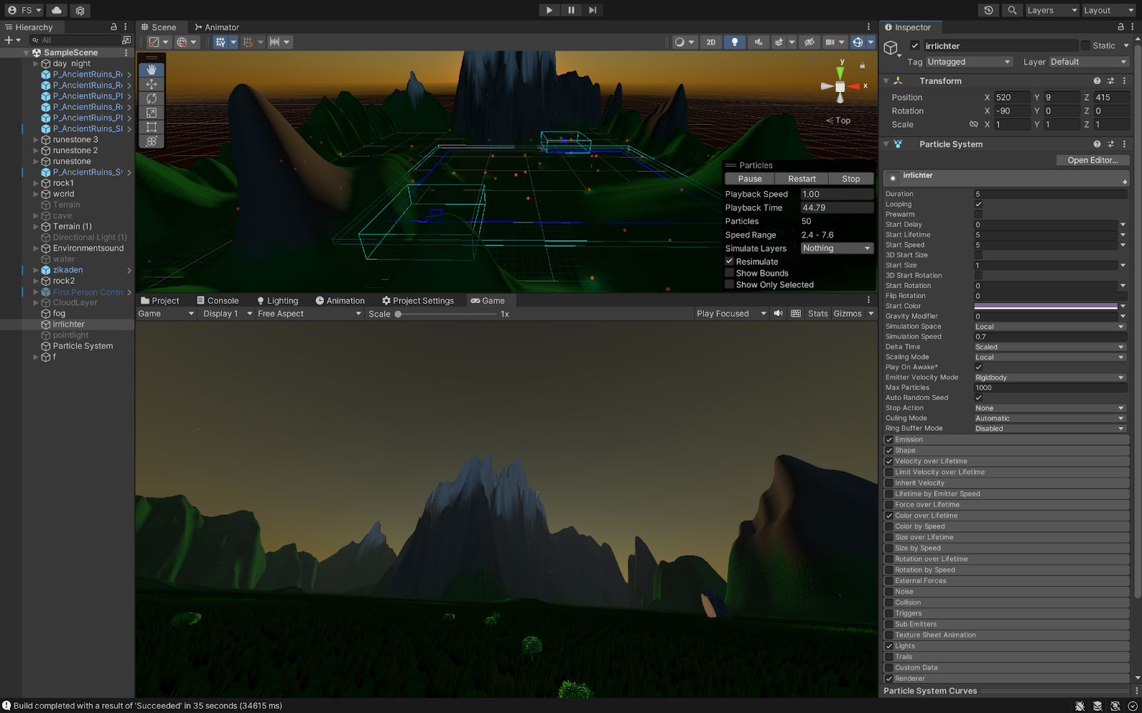
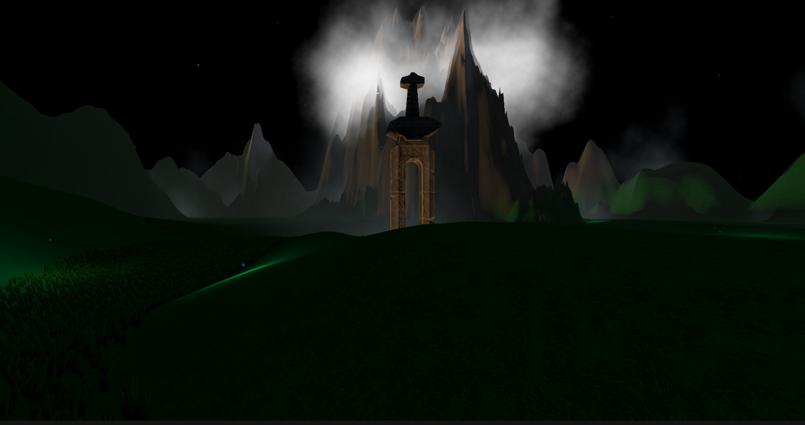
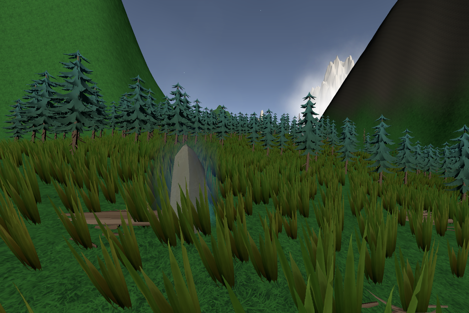
Visuell wurde die Welt, auch aufgrund der Rechenleistung der Oculusbrille, in einem einfachen Low-Poly-Stil gestaltet. Die Welt beinhaltet einige Berge, die schneebedeckt sind, dynamisch Wald- und Graslandschaften, Bauwerke aus Stein, ein Tag und Nacht System, Wolken, Nebel, die über das Unity-eigene Partikelsystem erstellt wurden. Der Unity Terrain Editor bietet eine einfache Bearbeitungsmöglichkeit für die Erstellung von Landschaften und Bergen, die man über ein Brush Tool einzeichnen kann. Für die grafische Verarbeitung musste viel Rücksicht auf die Leistungseinschränkungen der VR Brille genommen und genaue Vorgaben und Einstellungen in den Qualitätseinstellungen beachtet werden. Die eingebaute Renderpipeline war für das Projekt ausreichend.

The Swarm

Der Schwarm

Die Regeln, nach denen sich ein Schwarm verhält, können je nach Situation variieren, aber es gibt einige allgemein gültige Verhaltensmuster.

Schwärme beruhen in der Regel auf lokaler Kommunikation zwischen den Individuen und nicht auf zentraler Kontrolle. Dies ermöglicht es dem Schwarm, sich an veränderte Bedingungen anzupassen und Entscheidungen als Gruppe zu treffen.

Des Weiteren sind Schwärme in der Regel selbstorganisierend, was bedeutet, dass die Individuen im Schwarm sich selbst in Muster oder Strukturen anordnen, ohne dass eine zentrale Steuerung erforderlich ist.

Zudem trifft jedes Individuum eigene Entscheidungen auf der Grundlage von Informationen aus seiner lokalen Umgebung und dem Verhalten seiner Nachbarn.

Schwärme sind so konzipiert, dass sie gegenüber dem Ausfall einzelner Komponenten robust sind, so dass das Gesamtsystem auch dann noch funktioniert, wenn einige Individuen ausfallen.

Schwärme sind auch skalierbar, so kann die Anzahl der Individuen im Schwarm erhöht oder verringert werden, ohne das Gesamtverhalten des Systems zu beeinträchtigen. Auf Veränderungen in der Umgebung, z.B. an neue Hindernisse oder Änderungen der Missionsziele, kann sich ein Schwarm gut anpassen.

Für die Implementation in das Spiel wurden so folgende Regeln angewandt:

-Seperation: wähle eine Richtung, die einer Häufung an Individuen entgegenwirkt

-Angleichung: wähle eine Richtung, die der mittleren Richtung der benachbarten Boids entspricht

-Zusammenhalt: wähle eine Richtung, die der mittleren Position der benachbarten Boids entspricht

Um dies umzusetzen und zu erlernen wurde das Unity-eigene “Flocking-Tutorial” gewählt, dass in 3 Schritten den in den 60 Jahren von Craig Reynolds entwickelten KI-Algorithmus der Boids näherbringt.

The Swarm

Resonance Audio

Resonance ist ein von Google entwickeltes Software Development Kit (SDK) für räumliches Audio, mit dem Entwickler:innen realistische und immersive Audioerlebnisse für XR-Anwendungen schaffen können. Das SDK nutzt eine physikalisch basierte Simulation, die es Entwickler:innen ermöglicht, die Position und Bewegung von Schallquellen in der virtuellen Welt, sowie die Position und Ausrichtung der Zuhörer:innen zu steuern. 

Resonance Audio enkodiert einzelne Schallquellen in einen gemeinsamen Ambisonic-Stream, um sie anschließend als Summe in binauralem Format zu dekodieren und wiederzugeben. Dazu verwendet das SDK bis zu Third-Order-Ambisonic. Der Kodierungsprozess beginnt mit der Analyse der Richtwirkung, der Entfernung und der relativen Position der Schallquellen zu Hörer:innen. Das SDK verwendet diese Informationen, um die Amplitude und Phase der Schallquellen in jedem der Ambisonic-Kanäle zu berechnen.Es berücksichtigt ebenfalls die Reflexionen und den Nachhall des Schalls in der Umgebung und schließt dafür Parameter wie Reflexionskoeffizienten, Nachhallzeit, etc. ein.

Die HRTF (bzw. HRIR), die Resonance Audio verwendet, basiert auf einem KU 100 Kunstkopf. In der Dokumentation dazu wird der Verarbeitungsprozess beschrieben und eine Anleitung für das Monitoring gegeben, was aber für dieses Projekt nicht direkt relevant war, da die integrierte Fmod-Version genutzt wurde

Die von Google zur Verfügung gestellten HRTFs konnten eine Zeit lang nicht verändert werden da das SDK aber nun als OpenSource verfügbar ist, kann ein individueller Datensatz geladen werden. In der Verwendung als Fmod-Plugin sind keine HRTFs  individuell auswählbar.

Das SDK enthält außerdem eine Reihe von Funktionen und Tools, wie z.B. dynamisches Mischen, mit dem Entwickler:innen die Balance von Klängen in Echtzeit auf der Grundlage der Position und Ausrichtung des Zuhörers anpassen können und Raummodellierung, mit der Entwickler:innen virtuelle Räume erstellen können, die die Art und Weise beeinflussen, wie der Zuhörer den Klang wahrnimmt.

Google Resonance Audio wurde erstrangig für die Verwendung auf mobilen Endgeräten konzipiert und ist deswegen eine sinnvolle Entscheidung für die Entwicklung in einer VR-Umgebung.

Google Resonance Audio ist in FmodStudio als Plugin integriert und wird mit der Software geliefert. Um das SDK zu verwenden, muss es einfach in FmodStudio als Plugin ausgewählt und in den Bus eingefügt werden. 

Die Resonance AudioSource Komponente dient als Encoder der den Stream an den Resonance AudioListener sendet, den man auf den Masterbus platzieren sollte.

Sobald der Bus eingerichtet ist, können Entwickler:innen die FmodStudio Tools verwenden, um Events zu erstellen, diese zuweisen und im Mixingprozess die Klangquellen und die Position und Ausrichtung der Hörer:innen steuern.

Das Resonance Audio SDK bietet ebenfalls eine Funktion namens AudioRoom. Diese Räume werden in Unity eingerichtet und bieten realistische frühe Reflexionen und Hall, wobei die Materialien der Wände, des Bodens und der Decke berücksichtigt werden. Dies funktioniert über ein “Magnitude Spectrum Reverb”.

Um den AudioRoom in Unity zu verwenden, muss ein leeres Gameobjekt erstellt und diesem die FmodResonanceAudioRoom-Komponente zugeteilt werden.

Bei der Option Surface Materials können sechs akustische Oberflächenmaterialien gewählt werden.

Diese können über die Dropdown-Menüs nach Belieben geändert werden. Der Parameter Reflectivity steuert die Stärke der frühen Reflexionen im Raum. Die Reverb Properties beeinflussen den späten Nachhall im Hörraum (der als Schuhschachtel-Raum gehandhabt wird). 

The Swarm

Umsetzung

VR

Als VR-Brille wurde die Oculus Quest gewählt. Hintergrund dieser Entscheidung ist die einfache  Einbindung in Unity mithilfe des Oculus Integration Assets, welches ein geeignetes VR-Framework und ein einfach bedienbares Input-System in Unity ermöglicht.

Um auf einer VR Brille in Unity Spiele entwickeln zu können, müssen mehrere Faktoren berücksichtigt werden.

Die maximale Dateigröße für eine Oculus-App beträgt 4GB. Der Großteil des Speicherplatzes wird grafisch belegt, man sollte aber vor allem bei hochauflösenden Sounddateien diese Zahl im Hinterkopf behalten. Ebenso verfügt die Oculus Quest über eine begrenzte Prozessorleistung (ähnlich der eines Handys), darum sollte auch dementsprechend optimiert dafür entwickelt werden und alle Assets, die Unity lädt, für Android kompilierbar sein. In der Praxis bedeutet das, die Anzahl der High-Poly-Modelle zu reduzieren, mobile Shader und Texturen mit geringerer Auflösung zu verwenden und den Zeichenabstand für bestimmte Elemente zu verringern. Es wird auch empfohlen, die Anzahl der Lichter minimal zu halten, Schatten wenn nicht unbedingt nötig, zu deaktivieren und kein Postprocessing zu verwenden.

Unity

Unity bietet gute Grundvoraussetzungen für die Entwicklung von VR-Spielen, da es sich um eine plattformübergreifende Spiele-Engine handelt, die den Großteil der gängigen VR-Geräte unterstützt. Unity beinhaltet eine Vielzahl von Funktionen und Werkzeugen, die speziell für die Erstellung immersiver und interaktiver VR-Erlebnisse genutzt werden, z. B. physikbasierte Simulationen, fortschrittliche Beleuchtungs- und Partikeleffekte und ein Interaktionssystem. Entscheidendes Auswahlkriterium war die Verknüpfungsmöglichkeit mit FmodStudio und die Scripting API, die auch Anwender:innen ohne fundierte Kenntnisse das Programmieren ermöglicht.

FmodStudio

FmodStudio eignet sich für die Soundintegration in Unity, da es sich um eine stabile, leistungsstarke und vor allem für Education-Zwecke freie, Audio-Engine handelt. Sie ermöglicht die Erstellung von komplexen, dyamischen Audioszenarien auf eine intuitive und organisierte Weise und ist optisch ähnlich einer DAW aufgebaut.

Fmod verwendet Events, um mit Unity zu kommunizieren, da sie Flexibilität und Kontrolle darüber ermöglichen, wie Klänge im Spiel ausgelöst und gemischt werden.

Dazu kann in Unity einerseits das Event erstellt und verschiedene Triggerkonditionen eingestellt werden und für komplexere Konditionen kann es über ein Script getriggert werden. 

The Swarm

Ideenfindung

Durch Beobachtungen von Vogel- und Fischschwärmen über die Sommermonate, kam die Frage auf, ob man Soundobjekte ebenfalls so kohärent aufeinander wirkend durch einen Raum bewegen kann. Zu diesem Zeitpunkt war mir Ambisonic und objektbasiertes Audio noch wenig bekannt und ich stieß auf die Software “SoundParticles” der gleichnamigen Firma und simulierte ein solches System (ohne wirklich den Regeln einer Schwarmintelligenz zu folgen). 

Das Ergebnis war meiner Meinung schon ansehnlich, vor allem wenn man es über Kopfhörer wiedergab und seine Außenohrübertragungsfunktion (HRTF)

aus der Auswahl gefunden hat. 

SoundParticles wird üblicherweise in der Produktion von Filmen genutzt und rendert szenenbasiert. Das bedeutet zwangshalber, dass die Simulation zeitlich linear gerendert wird und Interaktion dadurch nicht möglich ist. Daraus entstand die Idee, eine Installation zu errichten, in der Benutzer:innen mit Schwärmen in Echtzeit in Aktion treten können. Das war im Anfangsstadium noch mit Infrarot-Headtracking und einer erweiterten Realität erdacht, relativ zeitgleich entwickelte sich aber auch mein Interesse an nichtlinearem Game-Audio und als ich in der Nachforschung über Headtracking von VR-Brillen auf die Gameengine Unity stieß, war die Brücke geschlagen. Von nun an richtete sich der Fokus auf Unity, VR-Integration und einem passenden Spatializer, dessen Entscheidung auf Googles Resonace Audio fiel. In der weiteren Entwicklung wurde die Audiomiddleware FmodStudio aufgrund der einwandfreien Kommunikation zwischen Unity und Resonance und den vielseitigen Bearbeitungsmöglichkeiten in der Middleware eingebunden.

Everything works (so far)!

Everything works so far! With the help of a very esteemed study colleague, the splitter and mixer were successfully soldered and started working. These achievements marked the start of many advances in the project. Now, the left and right hand setups could actually be tested completely, involving all necessary parts, soft- and hardware. Luckily, they worked as expected. The left hand setup is now able to switch between to FX loops according to fretting hand position and the right hand setup is able to control effect pedals via the expression pedal input. Finally, two boxes made from ABS plastic were bought at Neuhold to fit the ready-made circuits in a protected enclosure. Nine holes in total were drilled into the plastic for the audio jacks as well as the power supplies.

All applications need more testing and fine-tuning. The code of the left hand setup must be fine-tuned for example to work even more accurately at detecting frets and more pedals have to be tested in conjuncture with the right hand setup in order to find out what expressive effects are ideally controlled by the strumming hand. Additionally, some gimmicks may still be implemented at a later date. These include:

  • Variable threshold potentiometer
  • LED indicators (ON/OFF, etc.)
  • Battery monitor system for ESP32-LH/RH
  • One box
  • Box design

ESP32 between three devices

With the left hand setup working so well, it was finally time to integrate the ESP-NOW code into that of the right hand setup. So far, the ESP-NOW code only involves communication between two ESP32s. However, in the end the ESP32-CU should receive data from both devices, the ESP32-LH and the ESP32-RH. This means that ESP-NOW communication between three devices must be established. However, only one-way communication capabilities are necessary since the ESP32-LH/RH are the only ones to send data to the ESP32-CU with the latter sending no information back. Surprisingly, this made the code necessary a lot easier than it was before. Following a tutorial, the ESP32-CU was set up as the receiver (slave) and the other two ESP32s for left and right hand were set up as senders (masters). Then ESP-NOW communication was tested by sending dummy values from ESP32-LH and RH to the ESP32-CU. By sending a sender ID together with the dummy values, the ESP32-CU was not only capable of receiving the values but could also distinguish between the values sent by ESP32-LH and those sent by ESP32-RH. This was great news for the project!

With the basic code working, it was then time to add this new ESP-NOW code to the current codes of the left and right hand setups. As always, the ESP-NOW code was first added to the left hand setup code and it worked as expected. Next, the code was added to the right hand setup and communication between all three devices was tested simultaneously with the right hand and the left hand setup sending values to the ESP32-CU. This worked as well.

To top things off, the left hand setup was again fully tested in conjuncture with the digipot following the test setup explained in the previous blog post together with the new ESP-NOW code. This test worked as well making the Christmas holidays a very successful time for the project with much progress being made!

Sources:

ESP-NOW: Receive Data from Multiple ESP32 Boards (many-to-one) | Random Nerd Tutorials

Major left hand setup test

Unfortunately, no progress has been made with the hardware part of the project, namely the splitter and the mixer. Especially, the mixer evolved into an issue because the circuit built on the breadboard appears to be correct and even the project’s supervisor could find no error upon a brief inspection. However, despite all efforts, it does not seem to work properly and makes horrible noises when connected with its 9 Volts power supply… Nevertheless, as time pressure increased, it was decided to move forward and solder the mixer on a Veroboard instead of testing it on the breadboard – maybe it will start to work when all connection are firm. Consequently, two Veroboards were ordered.

In the meantime, it was decided to perform a major test of the left hand setup, involving all necessary components except said mixer. The idea was to have everything working so that when the mixer miraculously starts to functioning properly everything else already works and is ready to be tested in conjuncture with the mixer. The thorough the test of the left hand setup included several tasks.

Firstly, after some time off the headstock the ToF sensor was re-positioned again at the headstock of the test electric guitar and reconnect with the ESP32-LH (left hand setup). Then the ESP32-LH and the ESP32-CU (central unit) were re-paired using the ESP-NOW protocol. A change had to be made in the code of both ESP32s: so far, the ESP32-LH did all the processing of the ToF sensor values including computing the distances and the according frets, deciding if the Solo Mode has been activated or disactivated according to the fret threshold set and sending a corresponding message of 0 or 1 to the ESP32-CU. It was decided that the ESP32-LH should only be used to detect the frets and send the frets to the ESP32-CU who should then go on to decide over Solo Mode (dis-)activation based on fret threshold set and send 0 or 1. This comes with the advantage that if a flexible threshold can be set on the central hardware unit via a potentiometer, the ESP32-CU can receive this directly and the potentiometer values sending the fret threshold must not be send back to the ESP32-LH. This facilitates the code necessary because only a one-way communication is happening. After the relevant changes have been made in both codes, the setup was tested and it worked as expected. In the last step, the digipot was added. It was ordered to change between two resistance values depending on the status of the Solo Mode (ON = hand above 5th fret or OFF = hand below 5th fret). The resulting change in voltage was again detected by the trusted Arduino UNO whose serial monitor input was used as reference. This test worked as well: depending on the fretting hand position (below or above threshold of 5th fret) the resistance values changed. This basically means that the whole left hand setup is working. In the final setup, the change of the resistance values will be used to control the WET/DRY mix of the two FX loops.

Expression pedal

As mentioned before, it was decided that another design addition is to add an expression pedal output to the central hardware unit that can be used to control effect pedals featuring an expression pedal input. As things currently stand, the movements of the right, strumming hand will be the primary input for the expression pedal but, of course, also the left hand setup could be used as an control input. After the second semester, it was initially planned to control a virtual effect in Pure Data with the movements of the right hand. This would have necessitated the use of a laptop during live performances which is not really common among traditional guitarists. Consequently, the idea of using an expression pedal accords with the project’s goal to be easily implemented into a guitarists current live rig.

Developing the expression pedal was made possible with solving the problem of how to use the digital potentiometer MCP4251. As mentioned in the previous blog post, interfacing and using this digipot was made possible so, now, work on the expression pedal could commence. With the author not having too much experience with expression pedals and their functionality, some reading had to be done beforehand. Then, it was decided to firstly build a kind of conventional expression pedal using an analog potentiometer. By following the instructions of a blog post explaining how to build a DIY expression pedal from a Wah-Wah pedal, a circuit was made on a breadboard. This circuit involved a potentiometer which simulated the expression pedal (which is basically a potentiometer) that sent its values via a TRS line cable to an Arduino UNO that simulated the effect pedal controlled by the expression pedal. The Arduino UNO read the values coming in over the TRS cable using the analogRead() function. As the potentiometer was turned, the changing values sent over the TRS cable could be detected by the Arduino.

In the next step, the analog potentiometer was replaced by the digipot connected to an ESP32 and a code was written that toggled the resistance of the digipot between two values, changing every second. Thus, the ESP32 sent commands to change the resistance to the digipot. These voltage changes were then sent over the TRS cable to the Arduino UNO acting as the effect pedal and printed in the serial monitor of the Arduino. While this setup only simulated the workings of an expression pedal, it nevertheless proved that the components of the circuit worked together as desired. The next step here is to test the setup with actual IMU sensor input from the right hand while guitar playing AND to connect the setup not to the Arduino UNO but to an actual effect pedal with an expression pedal input.

Digital potentiometer

On 1st January, the digital potentiometer finally started working. As mentioned in previous posts, the idea is to use some sort of mixer to mix together two FX loops. The DRY/WET settings of this mixer should be controlled by the left hand setup. The mixer layout chosen for the project uses two analog potentiometers to mix the two guitar signals coming thru the FX loops. The issue is that analog potentiometers cannot be digitally controlled so a different solution had to be found. This solution is a digital potentiometer of the type MCP4251. This digipot has two digital potentiometers built in whose wipers can be set digitally by commands of a microcontroller. Getting this digipot to work however, was not that trivial. It works via SPI which is quite complicated, and no suitable library could be found at first. Additionally, it was not initially clear how to connect the MCP4251 with a microcontroller. After a lot of digging on the Internet, a project using this exact digipot was found. The author wrote a custom library that could be used, and he also explained how to wire up the MCP4252 to an Arduino UNO. Apparently, the Arduino UNO has specific SPI pins that need to be used for the SPI communication with the digipot. Following the instructions of the author’s blog post, the digipot could finally be used to control the brightness of two LEDs.

Next, a code was made to simulate the following mixing function that the MCP4251 will perform in the future:

  • Normal rhythm guitar mode (= fretting hand position < 5th fret)
    • FX loop 1 -> always 100% wet
    • FX loop 2 (containing delay etc.)  -> 20% wet
  • If Solo Mode active (= fretting hand position >= 5th fret)
    • FX loop 1 -> stays 100% wet
    • FX loop 2 (containing delay etc.) -> turned up to 50% wet

The WET/DRY status was simulated by changing the brightness of the two LEDs. This worked as well with the one LED’s brightness remaining unchanged while the other changed according to which fret was played on the guitar.

So far, the digipot was used in conjuncture with an Arduino UNO since this microcontroller was used in the tutorial. In the next step, it was tried to transfer the code to work on an ESP32. It was simpler than expected: the SPI pins of the ESP32 were determined and then everything worked as expected. Getting the digipot to work marked the achievement of another small milestone in the project as the digipot will serve as the main switching hardware controlling the WET/DRY ratio of the two FX loops via the input of the left hand setup and acting as an expression pedal via the input of the right hand setup.

.