MIDI BLE – the best way to transmit data?

After setting the main objectives for the third semester, the first issue that was tackled was the question of how to transmit the data. During the project, quite a few types of data transmissions have been tried out including USB-MIDI, only MIDI and, most recently, OSC.

As already mentioned in blog post #3, data transmission via OSC could be achieved using the ESP32’s WiFi capabilities. This means of communication comes with the definite advantage of being wireless, which was not possible with the MIDI setup from last semester.

However, my supervisor suggested trying out yet another possibility: MIDI via BLE (Bluetooth low energy). So basically, it sends MIDI over Bluetooth. Luckily, the ESP32 also has Bluetooth capabilities so it was possible to start experimenting immediately.

Using the MIDI-BLE library, a code was sketched that could transmit sensor data via MIDI via Bluetooth. Unfortunately, two additional, but free programs are necessary for MIDI BLE to work with Windows. One is called loopMidi which opens a specific MIDI port and the other program is called MIDIberry which lets you route the incoming MIDI signals to the aforementioned MIDI port. This MIDI port can then be selected as a MIDI input source in a DAW (I tested it with Cubase).

Apart from also being wireless, the MIDI BLE data transmission also comes with the additional advantage that it basically sends MIDI signals which work in every DAW almost straightaway while OSC support is not always given or that easy to use. For this very reason, it was decided to drop the OSC possibility for now and focus on MIDI BLE.

In Cubase, one can fully customize the parameter controls via MIDI. So, using Cubase, the “Solo Mode” that was previously written in a Pure Data sketch now works completely without the need for Pure Data since the effects that are turned on or off can now be directly selected in the DAW. This brings the project one more step closer to its completion.

However, while working in Cubase, the current solution does not (yet) work in Reaper for example. This is due to the fact that Reaper only uses the Learn MIDI function to map incoming MIDI CC messages to parameter controls. If two different CC messages are sent at the same time, meant for different effect types, it only recognizes one. It is then not possible to manually input another CC value to control another effect parameter as it is possible in the fully customizable Cubase.

As the two setups should be accessible without too much hassle for most guitarists, it must be established if other DAWs have the possibility of manually mapping MIDI CC values to parameter controls in order to ensure that this method, using MIDI BLE, works for at least the major DAW brands like Pro Tools, Ableton, Logic Pro, etc. if not for Reaper.
Objectives for the third semester

On 9th of October the first meeting of the third semester with my supervisor took place. We decided to meet to set the objectives to be reached during the third semester and to determine how the project and the two setups should be developed further.

The first question that arose was whether the focus of the development efforts should be placed on creative advancements of the tonal possibilities of the two setups (for example developing more effects to be controlled by the sensors’ data) or if the focus should be placed on fine-tuning the current setups and developing them into final products.

After some deliberation, it was decided to focus on further developing the existing setups into final products and pass on working on new tonal possibilities. As one of the goals of this project is to test the final setups on guitarists, it was deemed more important that the final setups should also look the part and function properly instead of having endless tonal possibilities but lacking in reliability and looks.

With the main focus of the final product phase set, it was decided to concentrate the development effort on three areas:

  1. Design of setup attachment
  2. Type of data transmission
  3. Software integration

These areas involve the following tasks:

  1. Design of setup attachment

Left hand setup:

  • 3D print cases for ToF sensor and microcontroller ESP32
  • Develop attachment device that is flexible enough to work on Fender AND Gibson headstock shapes
  • Extra knob for fret threshold setting
  • Extra knob for fine-tuning fret detection (?)
  • Determine power supply -> battery

Right hand setup:

  • 3D print cases for IMU sensor and microcontroller ESP32
  • Extra calibration button
  • Develop attachment -> use snap fasteners to clip sensor + microcontroller on
  • Determine power supply -> battery
  • Strong cover cable to connect sensor and microcontroller
  • Type of data transmission

Via OSC (current solution)

Pros:      wireless, already works

Cons:     integration in DAW more complicated (maybe different for every DAW)

Via Bluetooth + MIDI (BLE) (probably best solution)

Pros:      integration in DAW probably easier with “Learn MIDI”, ESP32 has Bluetooth

Cons:     does not work yet, fast enough? USB dongle necessary?

Via radio transmission (?)

  • Software integration

Goal: make setups useable within DAW

As already touched upon in previous blog posts, some experiments were done using the Camomile VST software. While achieving some success, it was still decided to abandon the idea of working with Camomile. On one hand, it was not possible to solve the issue of the effect not affecting the recorded signal. On the other hand, the Camomile environment was deemed impractical for the left hand setup.

Instead, the development efforts will focus on OSC or BLE + MIDI. Especially the latter solution appears to be promising because one could use the MIDI learn function that comes with practically any DAW that allows the user to use any plugins and customize controllable parameters within the DAW.

With these goals and focus areas set, the third project phase is really about to start. The first issue that will be tackled is determining the type of data transmission as well as the software integration.

Software integration test feat. Camomile VST

With both setups working via OSC, it was time to focus on another goal of the third project phase: the final software implementation. As stated before, the aim of this project is to further advance the sonic range of the electric guitar without impairing the guitar player’s natural playing. Although this statement mainly includes the natural playing style and associated hand movements of the player, its meaning could also be expanded to usability and how well the two setups can be integrated into the usual signal chain of the average guitar player.

The standard guitar signal chain is probably as follows:

Guitar into effect pedals into amp to microphone or interface

As both setups require a computer, implementing the setups into this signal chain will not be possible. However, a lot of guitarists nowadays will play straight into an interface + DAW or go from an amp into an interface + DAW. Hence, if the software of the project could be integrated into a DAW, it could be considered quite user-friendly for guitarists.

And here Camomile comes into play. Camomile is an audio plugin with Pure Data embedded, used to control patches inside a large set of digital audio workstations – as long as they support VST3 or Audio Unit formats. (1) It free, open-source and cross-platform and was developed by Pierre Guillot.

The plan is to convert the current Pure Data patches into VST plugins that can then be used in any DAW, making them more accessible and prone to be used by guitarists.

The left hand setup with its usage of third-party plugins seems not as suited at the moment, however, ways will be found to implement it as well. Nevertheless, for reasons of simplicity, it was decided to start with the right hand setup and try to make it work together with Camomile.

Luckily, Camomile comes with a WikiPage that explains how to generate plugins and also how to make new plugins. As far as I understood it, Camomile is sort of a platform that facilitates and enables communication between the Pure Data patch and DAW. In order to generate a VST plugin, one needs a folder that contains the Pure Data patch and sub-patches, the Camomile VST Plugin-File (instrument or effect), an info sketch in txt format and specific Pure Data sketches that facilitate communication between patch and DAW.

Within the text file, the parameters of the plugin, the in- and outputs and other factors need to be specified. For example, for the Wah-Wah effect patch, the following text was written:

  • param -name Frequency -label Hz -min 280 -max 3000 -default 1500;
  • param -name OSC -min 0 -max 1 -default 0 -nsteps 2;
  • iolayout 2 2;
  • code Bbbb;
  • type effect;
  • manufacturer Bjoern Bernreiter;
  • compatibility 1.0.7;

The first parameter is the center frequency of the Wah-Wah and the second on is the ON/OFF switch for the OSC reception.

Additionally, one must add the specifically written param.get, param.set and param.change sketches to one’s own sketch in order to ensure communication between patch and DAW.

Without going too much into detail, it was possible to generate a Wah-Wah plugin that can be opened in the DAW Cubase. The center frequency can be controlled via OSC with data coming from the IMU sensor. Furthermore, the parameters center frequency and OSC ON/OFF can be automated manually and in Write-Mode within the DAW.

However, there is one problem: While the center frequency can be automated when moving the slider while in Write-Mode or drawing in automation curves, it cannot be automated from the OSC data alone. Similarly, the Wah-Wah affects the tone of a guitar when played live, however, it does not affect it anymore after recording the guitar. These two issues are, of course, linked but so far, no solution could be found. On the upside, while searching for a solution, the Camomile plugin and its workings were understood much better.

Nevertheless, I am confident that this problem will be solved in the near future.

New attachment device for right hand setup

As stated in blog post #1, basic OSC transmission capabilities were achieved and thus, the IMU sensor’s data could now be transmitted via OSC to control the parameters of a Wah-Wah effect. The next step was to test this setup in conjuncture with real guitar playing. However, it was decided that a new attachment device for the ESP32 microcontroller was needed.

Prior to using OSC, the right hand setup used MIDI to transmit the sensor data from sensor + microcontroller to Pure Data. The IMU sensor was attached to the microcontroller (an Arduino Leonardo) via a long cable and the microcontroller itself was fitted onto a small housing with a MIDI jack attached to it.

With the ESP32 microcontroller now working wirelessly over OSC, there was no further need for the housing and the long cable. It was instead decided to fit the ESP32 on the right forearm of the guitar player with only a short cable connecting it to the IMU sensor which was still fitted onto the wristwatch. However, it proved difficult to find a way of attaching the sensor to the uneven surface of a human forearm. After some pondering of the issue, the idea was born to use an old sock to wrap around the arm onto which the ESP32, wrapped into a small bag of fabric, could subsequently be sewn. It must be stated that this means of attachment is not yet worthy of the name “final product” and another solution must be found. Nevertheless, for testing purposes the device sufficed. The Wah-Wah effect could be tested using OSC as a means of transmission and it worked as expected. Thus, it can be concluded that the right hand setup now works wirelessly which brings it closer to its ultimate goal of not impairing the guitarist’s natural playing style while still adding another dimension of sound to the guitar.

With the right hand setup working so well, it was time to transform the left hand setup in the same fashion and make it work wirelessly. Having established the basic OSC principles while working on the right hand setup, it was simply a matter of combining the original code made for the ToF sensor with the OSC code. The “new” left hand setup was then immediately tested using the previously made “Solo Mode” Pure Data patch and a guitar. As it was the case with the right hand setup, the wireless left hand setup seemed to work equally well as the MIDI-based setup.

While the transmission of data now works wirelessly via OSC, both setups still require to connect the respective sensors (IMU and ToF sensors) to the ESP32 microcontroller. With both sensor being relatively wide apart from each other, it is likely that two microcontrollers, one for each hand’s setup must be used for the final product.

Start of Product Phase & OSC Control

Hello and welcome back to my GPRO project as I like to call it. We are now entering the third semester already during which the prototype setups developed during the previous semester will be completed to final products. Instead of overthinking my next steps and planning too much ahead, I decided to jump right back in and continue where I stood at the end of the second semester.

As noted in the documentation and presentation of the second phase, both setups, in particular the right hand setup would benefit from being wireless, with no cables obstructing the guitar player’s movements. Hence, this was the first issue tackled. Although there exist several possibilities to send data wirelessly, it was quickly decided to try out OSC (open sound control) which works over WIFI.

Open Sound Control (OSC) is an open, transport-independent, message-based protocol developed for communication among computers, sound synthesizers, and other multimedia devices. OSC messages are transported across the internet and within local subnets using UDP/IP and Ethernet. Additionally, OSC is sometimes used as an alternative to the 1983 MIDI standard.

This decision was taken among other reasons because the author was provided with an ESP32 microcontroller at the end of the second semester by his supervisor which already has WIFI capabilities on board. As the name already suggests, the ESP32 is not an Arduino product, however, it still can be programmed using the Arduino IDE after conducting a manual implementation process. With only a few difficulties, said process was completed and the ESP32 ready to be programmed.

The first step was to write an Arduino sketch which connects the ESP32 to the local WIFI network of the author in order to be able to send OSC messages. Using the OSC library for Arduino, such a code was achieved in a rather short time. Furthermore, the OSC library also contained a very useful example sketch to send OSC messages which served as a great learning tool to understand how OSC messaging works. In order to test the OSC messaging function, a Pure Data patch was made which uses the “netreceive” and “oscparse” objects among others to receive OSC messages coming in from a predefined port. The “netreceive” objects allows Pure Data to listen to a specific port, in this case 8000. In the Arduino sketch the port 8000 was defined as the outport from which OSC messages are sent. As a result, OSC messages could now be sent from the ESP32 via WIFI to Pure Data.

After achieving basic OSC messaging capabilities, the subsequent step was to merge the original sketch for the right hand setup, containing the code to access the IMU data readings, with the new OSC messaging method. On the other hand, the Pure Data patch from the second semester which is set up to receive the y-value of the orientation data from the IMU sensor to control a Wah-Wah effect was updated was well. Instead of receiving the orientation data as MIDI input, it now receives the orientation data via OSC, using the objects mentioned above.

After establishing the pin layout of the ESP32, the IMU sensor (still attached to the wrist watch device) could be connected to the microcontroller and data transmission from the ESP32 to Pure Data was successful. Latency seemed to be comparable to that of MIDI. With basic OSC transmission working, it is time to test the new setup it in conjuncture with real guitar playing.

Source:

OSC spec 1_0 (stanford.edu)

Future Plans

As it is not always possible to set up a network communication with Bela, I plan to make the physical interface completely independent from the OSC control to avoid any usability issues. To achieve this, I will add a toggle switch to the physical interface, which will allow for the selection of the effects. Additionally, I will add an RGB LED to the interface, which will always display the color of the effect in use. For this, I might have to change to the larger Bela, as the mini version I am currently using doesn’t offer any analog outputs. Another benefit of the larger Bela over the Bela Mini is that it includes a line out in addition to the normal audio out, meaning I could have an extra headphone out on the unit.

I also plan to expand the OSC interface, so it can offer more detailed parameter settings. One idea is to include presets, which can be saved and recalled at any time. Additionally, I would integrate a tuner that is only accessible in the OSC interface. As already mentioned I will try to solve the issues with the convolution algorithm, so I can load Impulse Responses, which would also only be available in the OSC interface. Finally, as this is an open-source project, I also plan to set up a Git Repository, where I provide all the material and information necessary to reproduce this project.

The Physical Interface

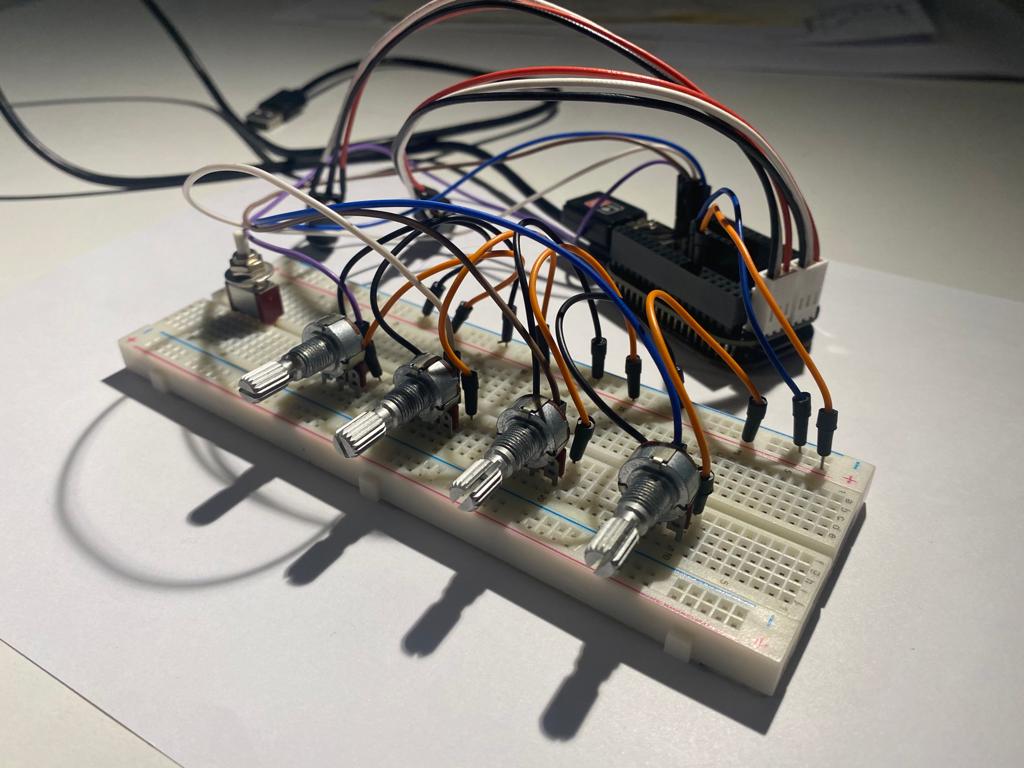
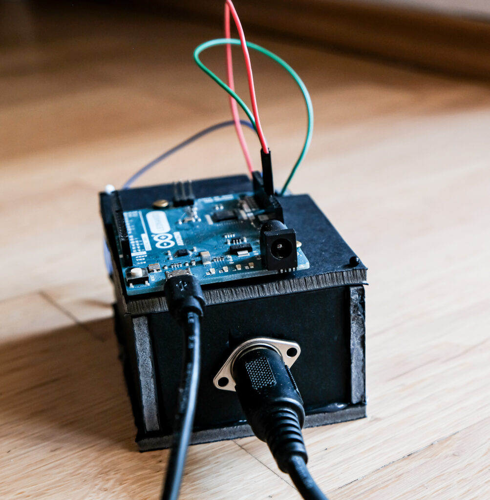
Since I also wish to develop a physical interface in addition to the OSC control, I built a prototype to experiment with the possibilities. I want to keep the interface as simple as possible, so I set up only 4 potentiometers that allow the control of one effect at a time. To read the potentiometers from the analog inputs on Bela, I had to add a piece of code for each input in PD. As Bela handles analog inputs just as audio signals at the sampling rate, I had to set up an [adc~] object for each potentiometer respectively. The first 2 channels are reserved for the audio signal, but from 3 to 10, I was able to access the required analog inputs.

To convert the incoming values into numbers, I used the [snapshot~] object which takes a signal and converts it to a control value whenever it receives a bang in its left inlet. To make it output the value constantly, I connected a [metro] object to it, which bangs it continuously at a specified rate. After receiving a value between 0 and 1 from each potentiometer, I could already control all parameters manually. For those that need a range other than 0 to 1, I set up math calculations to translate the values to the required ones. Next, I set up a structure that routes the corresponding set of values to the selected effect.

To choose which effect is set on the physical interface I added a button to each unit in the OSC interface. These are then connected to their respective [spigot] objects in PD, which only pass the signal when the switch is on, thus routing the control values to the selected effect. Because the analog input values come in at a constant rate, they immediately force their initial value on the selected parameters. This leads to a conflict with the OSC interface as its values are always forced to the analog ones. To solve this problem, I implemented an if statement for all parameter sets, which immediately disconnects the physical interface in case there is a change within the OSC interface of the respective effect.

Failed experiments

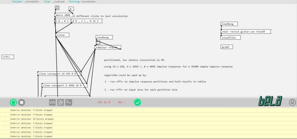
My next ambition was to add a convolution algorithm to the patch, so I can load impulse responses and achieve different kinds of reverbs, amp simulations, and special effects. There are various convolution externals for PD but my limitation, as usual, was the Vanilla library again. I tried uploading the externals to the same folder as the patch, but even so, all of them got rejected in the IDE.

The only vanilla-compatible solution I’ve found so far is a low-latency partitioned convolution algorithm by Tom Erbe. His patch should normally work on Bela, but since it uses the read-skip function to partition the IR sample 28 times, it requires a lot of processing power, exceeding Bela’s capacity and causing CPU overload. Erbe suggests that the convolution process can be sped up by either running [rfft~] on the impulse response partitions and storing the results in tables, or running [rfft~] on the input once for each partition size but unfortunately I haven’t been able to solve this issue yet.

Adding additional effects

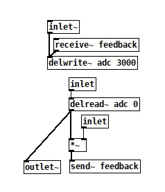
As all my experiments were completed with success so far, I was now able to add more effects to the chain by implementing the same well-tried principles. Based on my initial intention concerning the analog delay chain, I decided to add both a delay and a reverb effect to the patch. The delay is also based on the [delwrite~] and [delread~] objects and follows the principles of any usual digital delay pedal. The input signal gets delayed in the buffer with an amount between 0 and 3000 milliseconds which is then routed to the output. The input is also sent straight to the output where it gets mixed with the delayed signal. To create feedback, the delay signal is once fed back to the input, but as its level is always less than one its volume will decay over time.

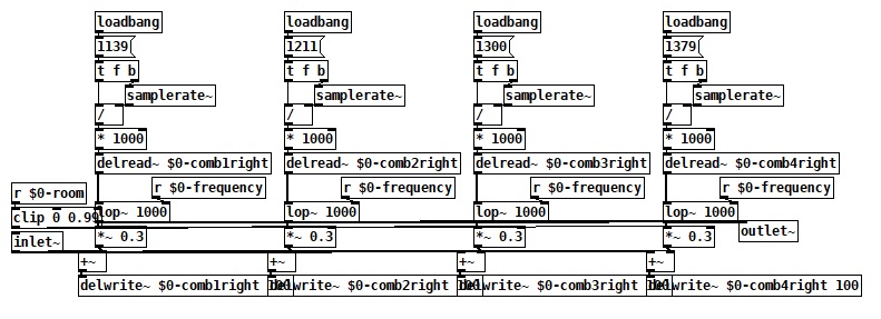
To build the reverb, I first tried to use the [rev1~] object, thinking it was part of the vanilla library. After I uploaded the patch to Bela, it turned out to be unsupported, so I had to find a Vanilla-friendly solution. Following some research, I learned that Katja Vetter made a freeverb abstraction only with Vanilla objects, but I couldn’t find the original patch, only an adapted version by Derek Kwan. As this project was available on GitHub and free to use, I implemented it into my project. Similar to my delay line, this patch also uses a series of comb filters implemented with the [delread~] objects to modulate the signal. In addition, a low-pass filter is applied to the taps, creating the opportunity to attenuate the reverb. Having previously set up all the networking structures for the OSC protocol, all I had to do was add the new parameters to both the TouchOSC interface and the PD patch and everything was up and running.

Adding control – Implementing OSC

Once this was working properly, I could move on to my third experiment and add a control interface to the system. Having previously researched and gained practical knowledge about the Open Sound Control (OSC) protocol, it remained the obvious choice for this application as well. Since I already purchased the TouchOSC mobile application earlier, I decided to use it for this experiment, but because it is not a free software I am going to implement another one for the final product. Two notable possibilities are PDParty and MobMuPlat, which are both open-source applications capable of running Pure Data patches and integrating the OSC protocol. The only advantage of MobMuPlat over PDParty is that the latter is only available for iOS, which considering integrability may be a significant issue.

To set up communication between my phone and Bela, I first had to make sure that it can connect to the internet/wi-fi. Since Bela is a Linux computer with USB connectivity, the best solution was to connect a WiFi dongle to it. Not any dongle is suitable for this application, so I had to find one that is Linux compatible. All dongles should work, which include the 4.4.113 Linux kernel in their driver, but two drivers that were tested and proven are the Ralink RT5370 and MT7601U. One option that was relatively easy to purchase and includes the RT5370 driver is the MOD-WIFI-R5370 from OLIMEX.

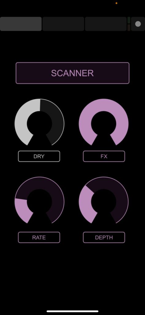
To get it working, I had to connect to Bela by running ssh root@bela.local from a terminal on my computer. After I was connected, I could make sure that the dongle was visible on the board. As the connection was successful by itself, I didn’t have to install any additional driver or edit the interface settings, I just had to set the name and password of my network and reboot. Now that Bela was connected to the same WiFi as my phone, I was able to set up an OSC communication between the two. The first step was to design a control interface in the TouchOSC editor, which had the same parameters as the Pure Data patch. As I needed to control the values for rate, depth, and both wet and dry signals, I created a slider for each and set up their range according to the PD patch. To be able to route these values later in PD, I also had to give each slider a corresponding name.

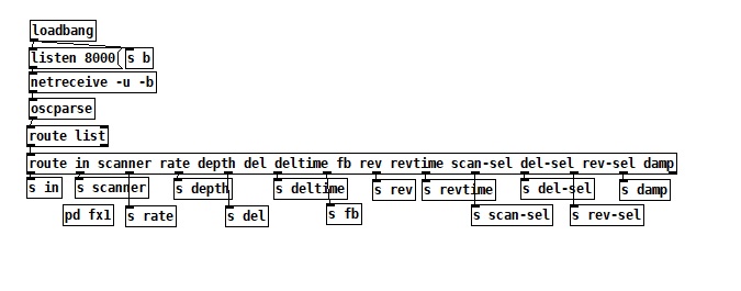
The second step was to add the [netreceive~] object to the Pure Data patch, which listens for incoming network messages on a given port. These values are then transmitted to the [oscparse~] object which reconstructs them into OSC messages. This is then fed into a [route] object, which checks the first element of a message against each of its arguments and if a match is found, the rest of the message appears on the corresponding outlet. After routing all values to their correct destination I only had to set Bela’s IP address as the host in the TouchOSC app and I was finally ready to try out the scanner patch with adjustable settings.

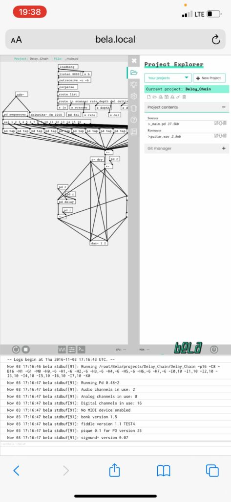
Setting up a connection with Bela is quite simple in the majority of the cases, but there are some situations in which it is not possible. One of these unfortunate circumstances is when the name of the network consists of more words separated by space. Another is when a username has to be specified in addition to the network name and password. Both of these problems stem from how the network credentials are defined in the terminal. One solution I found to this problem was to set up a hotspot connection between my phone and Bela, but even in this case, I needed to connect my phone to a WiFi network for the OSC messages to be forwarded. However, a great advantage of Bela is the easily accessible IDE, not only on a computer, but via any smartphone’s browser, which opens up the possibility of selecting multiple sets of patches stored on the device.