Evaluation of a master’s thesis submitted to a foreign University

For the third task of the Proseminar Master’s Thesis course, I have chosen to evaluate Yasmeen Sultana’s master’s thesis entitled “Open-Source Audio Platform for Embedded Systems” submitted for the degree of Master of Science in Information Technology at the University of Applied Sciences Kiel in 2018.

The evaluation is based on the following criteria:

Level of design

The composition of the work is formal and thus fits very well with its technical character. The title and subtitle are very well formatted, making the text easy to follow. Figures and tables are placed and scaled correctly and therefore blend into the structure perfectly.

Degree of innovation

The work has a great degree of innovation as it delivers new audio software built upon open-source technologies. The development of this software is a considerable contribution to the open-source community and can be further used or built upon.

Independence

The work is an original and innovative idea based on independent research and interest. The technologies used are given, but the work expands their capabilities and thereby can be considered innovative.

Outline and structure

The work is clearly structured and therefore easy to follow and understand. The chapters are logically ordered and correspond perfectly to the table of content while a list of figures, a list of abbreviations, and a list of tables are also included.

Degree of communication

Although the language used in this work is scientific, it is easy to understand because the sentences are logically worded. The author remains factual throughout the text and never uses the 1st person. 

Scope of the work

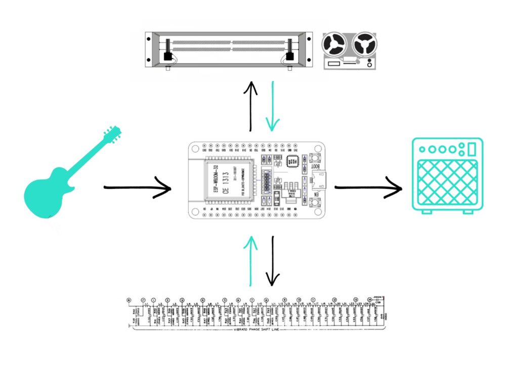
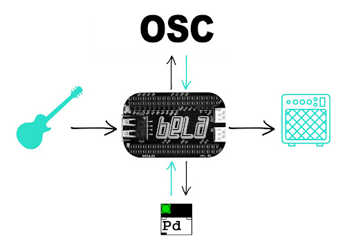
The work encompasses both a practical and a theoretical part. First, the technical background is presented, introducing all the theoretical knowledge needed to carry out this project. This is followed by the technical implementation of the hardware setup, followed by the evaluation of the product, and a discussion about the results. 

Orthography and accuracy

I’m not a native English speaker, but based on my knowledge, I found the text very coherent and did not find any spelling mistakes or other orthographic errors.

Literature

The author mainly uses specialist literature from the fields of audio and digital signal processing. Wikipedia articles are also used as a source, which is a bit surprising but does not undermine the quality of the work.

References:

  1. Sultana, Yasmeen. “Open-Source Audio Platform for Embedded Systems,” 2018. https://www.creative-technologies.de/wp-content/uploads/2018/01/Open-Source-Audio-Platform-for-Embedded-Systems.pdf. 

Future Plans

As it is not always possible to set up a network communication with Bela, I plan to make the physical interface completely independent from the OSC control to avoid any usability issues. To achieve this, I will add a toggle switch to the physical interface, which will allow for the selection of the effects. Additionally, I will add an RGB LED to the interface, which will always display the color of the effect in use. For this, I might have to change to the larger Bela, as the mini version I am currently using doesn’t offer any analog outputs. Another benefit of the larger Bela over the Bela Mini is that it includes a line out in addition to the normal audio out, meaning I could have an extra headphone out on the unit.

I also plan to expand the OSC interface, so it can offer more detailed parameter settings. One idea is to include presets, which can be saved and recalled at any time. Additionally, I would integrate a tuner that is only accessible in the OSC interface. As already mentioned I will try to solve the issues with the convolution algorithm, so I can load Impulse Responses, which would also only be available in the OSC interface. Finally, as this is an open-source project, I also plan to set up a Git Repository, where I provide all the material and information necessary to reproduce this project.

The Physical Interface

Since I also wish to develop a physical interface in addition to the OSC control, I built a prototype to experiment with the possibilities. I want to keep the interface as simple as possible, so I set up only 4 potentiometers that allow the control of one effect at a time. To read the potentiometers from the analog inputs on Bela, I had to add a piece of code for each input in PD. As Bela handles analog inputs just as audio signals at the sampling rate, I had to set up an [adc~] object for each potentiometer respectively. The first 2 channels are reserved for the audio signal, but from 3 to 10, I was able to access the required analog inputs.

To convert the incoming values into numbers, I used the [snapshot~] object which takes a signal and converts it to a control value whenever it receives a bang in its left inlet. To make it output the value constantly, I connected a [metro] object to it, which bangs it continuously at a specified rate. After receiving a value between 0 and 1 from each potentiometer, I could already control all parameters manually. For those that need a range other than 0 to 1, I set up math calculations to translate the values to the required ones. Next, I set up a structure that routes the corresponding set of values to the selected effect.

To choose which effect is set on the physical interface I added a button to each unit in the OSC interface. These are then connected to their respective [spigot] objects in PD, which only pass the signal when the switch is on, thus routing the control values to the selected effect. Because the analog input values come in at a constant rate, they immediately force their initial value on the selected parameters. This leads to a conflict with the OSC interface as its values are always forced to the analog ones. To solve this problem, I implemented an if statement for all parameter sets, which immediately disconnects the physical interface in case there is a change within the OSC interface of the respective effect.

Failed experiments

My next ambition was to add a convolution algorithm to the patch, so I can load impulse responses and achieve different kinds of reverbs, amp simulations, and special effects. There are various convolution externals for PD but my limitation, as usual, was the Vanilla library again. I tried uploading the externals to the same folder as the patch, but even so, all of them got rejected in the IDE.

The only vanilla-compatible solution I’ve found so far is a low-latency partitioned convolution algorithm by Tom Erbe. His patch should normally work on Bela, but since it uses the read-skip function to partition the IR sample 28 times, it requires a lot of processing power, exceeding Bela’s capacity and causing CPU overload. Erbe suggests that the convolution process can be sped up by either running [rfft~] on the impulse response partitions and storing the results in tables, or running [rfft~] on the input once for each partition size but unfortunately I haven’t been able to solve this issue yet.

Adding additional effects

As all my experiments were completed with success so far, I was now able to add more effects to the chain by implementing the same well-tried principles. Based on my initial intention concerning the analog delay chain, I decided to add both a delay and a reverb effect to the patch. The delay is also based on the [delwrite~] and [delread~] objects and follows the principles of any usual digital delay pedal. The input signal gets delayed in the buffer with an amount between 0 and 3000 milliseconds which is then routed to the output. The input is also sent straight to the output where it gets mixed with the delayed signal. To create feedback, the delay signal is once fed back to the input, but as its level is always less than one its volume will decay over time.

To build the reverb, I first tried to use the [rev1~] object, thinking it was part of the vanilla library. After I uploaded the patch to Bela, it turned out to be unsupported, so I had to find a Vanilla-friendly solution. Following some research, I learned that Katja Vetter made a freeverb abstraction only with Vanilla objects, but I couldn’t find the original patch, only an adapted version by Derek Kwan. As this project was available on GitHub and free to use, I implemented it into my project. Similar to my delay line, this patch also uses a series of comb filters implemented with the [delread~] objects to modulate the signal. In addition, a low-pass filter is applied to the taps, creating the opportunity to attenuate the reverb. Having previously set up all the networking structures for the OSC protocol, all I had to do was add the new parameters to both the TouchOSC interface and the PD patch and everything was up and running.

Adding control – Implementing OSC

Once this was working properly, I could move on to my third experiment and add a control interface to the system. Having previously researched and gained practical knowledge about the Open Sound Control (OSC) protocol, it remained the obvious choice for this application as well. Since I already purchased the TouchOSC mobile application earlier, I decided to use it for this experiment, but because it is not a free software I am going to implement another one for the final product. Two notable possibilities are PDParty and MobMuPlat, which are both open-source applications capable of running Pure Data patches and integrating the OSC protocol. The only advantage of MobMuPlat over PDParty is that the latter is only available for iOS, which considering integrability may be a significant issue.

To set up communication between my phone and Bela, I first had to make sure that it can connect to the internet/wi-fi. Since Bela is a Linux computer with USB connectivity, the best solution was to connect a WiFi dongle to it. Not any dongle is suitable for this application, so I had to find one that is Linux compatible. All dongles should work, which include the 4.4.113 Linux kernel in their driver, but two drivers that were tested and proven are the Ralink RT5370 and MT7601U. One option that was relatively easy to purchase and includes the RT5370 driver is the MOD-WIFI-R5370 from OLIMEX.

To get it working, I had to connect to Bela by running ssh root@bela.local from a terminal on my computer. After I was connected, I could make sure that the dongle was visible on the board. As the connection was successful by itself, I didn’t have to install any additional driver or edit the interface settings, I just had to set the name and password of my network and reboot. Now that Bela was connected to the same WiFi as my phone, I was able to set up an OSC communication between the two. The first step was to design a control interface in the TouchOSC editor, which had the same parameters as the Pure Data patch. As I needed to control the values for rate, depth, and both wet and dry signals, I created a slider for each and set up their range according to the PD patch. To be able to route these values later in PD, I also had to give each slider a corresponding name.

The second step was to add the [netreceive~] object to the Pure Data patch, which listens for incoming network messages on a given port. These values are then transmitted to the [oscparse~] object which reconstructs them into OSC messages. This is then fed into a [route] object, which checks the first element of a message against each of its arguments and if a match is found, the rest of the message appears on the corresponding outlet. After routing all values to their correct destination I only had to set Bela’s IP address as the host in the TouchOSC app and I was finally ready to try out the scanner patch with adjustable settings.

Setting up a connection with Bela is quite simple in the majority of the cases, but there are some situations in which it is not possible. One of these unfortunate circumstances is when the name of the network consists of more words separated by space. Another is when a username has to be specified in addition to the network name and password. Both of these problems stem from how the network credentials are defined in the terminal. One solution I found to this problem was to set up a hotspot connection between my phone and Bela, but even in this case, I needed to connect my phone to a WiFi network for the OSC messages to be forwarded. However, a great advantage of Bela is the easily accessible IDE, not only on a computer, but via any smartphone’s browser, which opens up the possibility of selecting multiple sets of patches stored on the device.

Turning Bela into a guitar effect

My next experiment was to turn the Bela board into a guitar effect and integrate the scanner into it. Bela has both built-in audio input and output, which can be addressed with the [adc~] and [dac~] objects respectively. By assigning an [adc~] to the input of the [delwrite~] object and a [dac~] to the output of the delay taps, I could run the signal from my guitar through the patch and hear the effect in action on my headphones or in my guitar amp.

To upload and run a PD patch on Bela, all I had to do was access its web-based IDE by addressing bela.local in my web browser and make sure to name the file _main.pd. Since the patch is no longer editable in the IDE, I couldn’t change any of the effect’s parameters, so I set up a patch with default values to test if the sound comes through Bela and if the patch works.

Scanner Vibrato simulation in Pure Data

To simulate Hammond’s vibrato scanner unit in Pure Data, I first had to find a way to replicate the delay line. Although there are many externals including all-pass and comb filters that would be suitable for this purpose, I had to keep in mind that BELA supports only Vanilla objects so I had to work with a limited library.

An obvious starting point was to use the [delwrite~] object, which allocates memory to a buffer and writes an audio signal into it. This signal is then read by the [delread~] object of the same name with a variable delay time, which can be defined in milliseconds. As it is possible to use more than one [delread~] object for the same buffer, I was able to set up multiple delay taps for the same signal, where each step is being delayed by 5 milliseconds relative to the previous one. Mixing these with the original signal results in amplification and cancellations at regular intervals, producing a comb filter in the end.

Next, I built a mechanism based on the scanner that could sample these delay taps. To do this, I first created a simple counter that increments by one with a specified velocity and then starts over when the given maximum value is reached. Its value is then passed to a select object, which sends a bang to the corresponding outlet when the value matches its argument. This results in a sequencer actually, which is ultimately what the scanner also is.

To connect the delay line to the sequencer, I placed a [vline~] object at the output of each tap. [Vline~] creates linear ramps whose levels and timing are determined by the messages you send. By creating a ramp-up and ramp-down message for each [vline~] object, I was able to toggle the volume of the taps on and off in a specific order so that each successive bang increases the volume of its assigned tap while turning down the previous one. To make sure that there is always a smooth transition between the taps, I made the duration of the ramps relative to the speed of the sequencer’s clock, achieving a perfect crossfade at any given rate.

To adjust the depth of the fades, I do multiplications on the ramp value that is sent to the [vline~] with a value between 1 and 5. The larger this number, the less accentuated the ramps are, and the smaller the depth is. This also means that the smaller the depth, the more the taps get mixed, which results in a chorus effect subsequently. Additionally, by mixing the dry signal with the scanner, a chorus-vibrato can be achieved, just as in the original Hammond design.

The original scanner

My first experiment was to simulate the delay line with Pure Data, based on the research carried out in the previous phase of this project. Originally, the analog delay line is part of the Hammond Vibrato Scanner unit and it incorporates a series of second-order audio filter stages where each stage is shifted in phase relative to the previous one. This results in an increasing time delay between every successive step of the line (about 50μs per filter stage). This is then fed into a scanner, which is a single-pole 16-throw air-dielectric capacitor switch connecting nine selected taps from the line to the output.

As the scanner gradually transitions between these taps, it alternates the phase shift applied to the sound, causing slight variations to the pitch that result in a vibrato effect. The depth of the vibrato depends on the width of the frequency shift fed into the scanner, which means that scanning about one-third of the delay line would produce a lighter vibrato effect while scanning the whole line would significantly increase its depth. In addition to the vibrato, a chorus effect can also be achieved by mixing the dry input signal with multiple outputs on the delay line, or a chorus-vibrato by mixing the dry signal with the output of the vibrato.

A work in progress

Initially, I proposed the development of an analog multi-effects chain unit that combines different types of vintage audio components with the capabilities of modern microcontrollers. The core element of this device would have been an analog delay line which, when sampled in different sequences, produces different modulation effects. The unit could be expanded with additional analog modules such as spring reverbs and tape delays daisy-chained in interchangeable order and controlled by the same central ESP32 microcontroller. The user interface would be divided between a minimalist control panel on the device and a mobile app that allows for detailed parameter settings.

Due to difficulties in designing an analog circuit that could sample the delay line, I decided to take my project to the digital domain and create a digital multi-effects chain instead. After gaining extensive experience with Pure Data and the Bela Board in the first part of this semester, I decided to use these technologies for the project. The main plan remained essentially the same as proposed in the first semester, only the hardware had been replaced.

My new plan is to establish a community-oriented product by incorporating various open-source technologies. I propose the development of a digital multi-effect unit that combines the flexibility of Pure Data with the ultra-low latency of Bela and the integrability of the open sound control protocol. The core element of the effect chain is a delay line that produces different modulation effects. By design, the unit can be expanded with additional effect modules that are controlled by the same open sound control interface.